Nissan Pathfinder (2007 year). Manual - part 223
IGNITION SIGNAL
EC-651
C
D
E
F
G
H
I
J
K
L
M
A
EC
2007 Pathfinder
5.
CHECK IGNITION COIL POWER SUPPLY CIRCUIT-II
1.
Turn ignition switch OFF.
2.
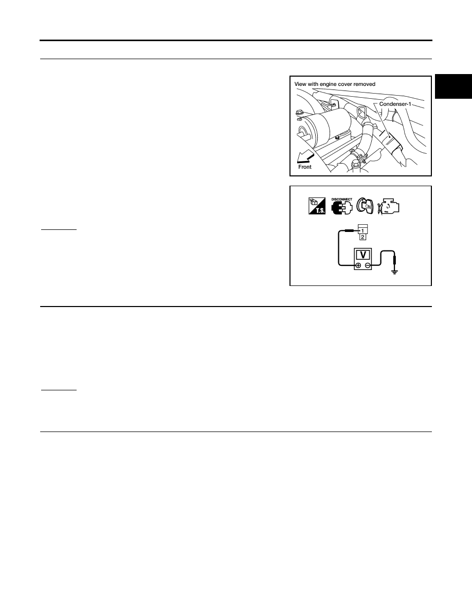
Disconnect condenser-1 harness connector.
3.
Turn ignition switch ON.
4.
Check voltage between condenser-1 terminal 1 and ground with
CONSULT-II or tester.
OK or NG
OK
>> GO TO 8.
NG
>> GO TO 6.
6.
CHECK IGNITION COIL POWER SUPPLY CIRCUIT-III
1.
Turn ignition switch OFF.
2.
Disconnect IPDM E/R harness connector E119.
3.
Check harness continuity between IPDM E/R terminal 3 and condenser-1 terminal 1.
Refer to Wiring Diagram.
4.
Also check harness for short to ground and short to power.
OK or NG
OK
>> GO TO 17.
NG
>> GO TO 7.
7.
DETECT MALFUNCTIONING PART
Check the following.
●
Harness connectors E2, F32
●
Harness for open or short between condenser-1 and IPDM E/R
>> Repair open circuit or short to ground or short to power in harness or connectors.
BBIA0562E
Voltage: Battery voltage
PBIB0624E
Continuity should exist.