Nissan Pathfinder (2007 year). Manual - part 221


  Index      Manuals     Nissan Pathfinder (2007 year) - Service and Repair Manual


Search            copyright infringement  


Content      ..     219      220      221      222     ..


Nissan Pathfinder (2007 year). Manual - part 221


FUEL INJECTOR

EC-635

C

D

E

F

G

H

I

J

K

L

M

A

EC

2007 Pathfinder

7. 

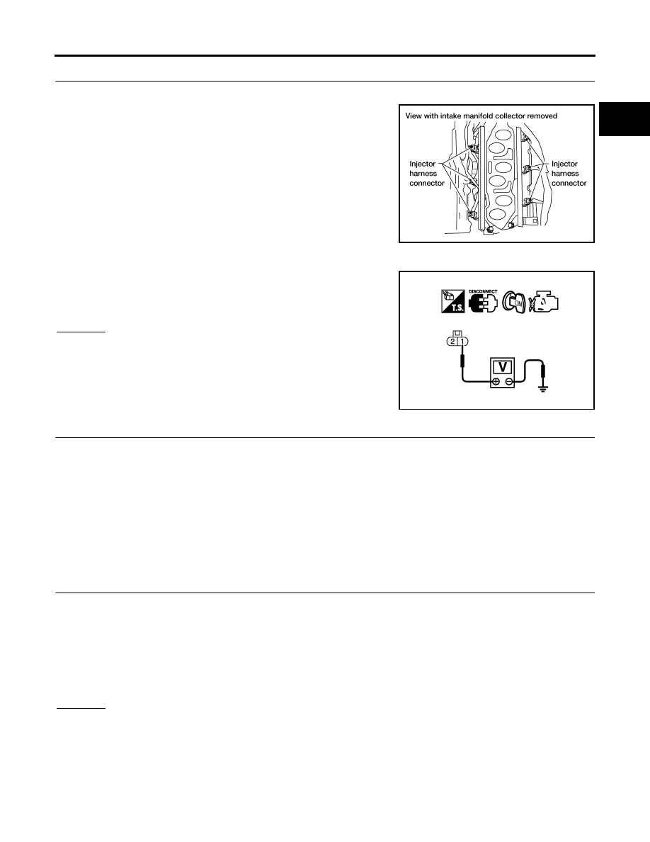
CHECK FUEL INJECTOR POWER SUPPLY CIRCUIT

1.

Turn ignition switch OFF.

2.

Disconnect fuel injector harness connector.

3.

Turn ignition switch ON.

4.

Check voltage between fuel injector terminal 1 and ground with
CONSULT-II or tester.

OK or NG

OK

>> GO TO 9.

NG

>> GO TO 8.

8. 

DETECT MALFUNCTIONING PART

Check the following.

Harness connectors E2, F32

Harness connectors F44, F101

IPDM E/R harness connector E119

15A fuse

Harness for open or short between fuel injector and fuse

>> Repair harness or connectors.

9. 

CHECK FUEL INJECTOR OUTPUT SIGNAL CIRCUIT FOR OPEN AND SHORT

1.

Turn ignition switch OFF.

2.

Disconnect ECM harness connector.

3.

Check harness continuity between fuel injector terminal 2 and ECM terminals 21, 22, 23, 40, 41, 42. 
Refer to Wiring Diagram.

4.

Also check harness for short to ground and short to power.

OK or NG

OK

>> GO TO 11.

NG

>> GO TO 10.

BBIA0546E

Voltage: Battery voltage

PBIB0582E

Continuity should exist.

EC-636

FUEL INJECTOR

2007 Pathfinder

10. 

DETECT MALFUNCTIONING PART

Check the following.

Harness connectors F101, F44

Harness for open or short between fuel injector and ECM

>> Repair open circuit or short to ground or short to power in harness or connectors.

11. 

CHECK FUEL INJECTOR

Refer to 

EC-636, "Component Inspection"

  .

OK or NG

OK

>> GO TO 12.

NG

>> Replace fuel injector.

12. 

CHECK INTERMITTENT INCIDENT

Refer to 

EC-145, "TROUBLE DIAGNOSIS FOR INTERMITTENT INCIDENT"

  .

>> INSPECTION END

Component Inspection

UBS00KIA

FUEL INJECTOR

1.

Disconnect injector harness connector.

2.

Check resistance between terminals as shown in the figure.

Removal and Installation

UBS00KIB

FUEL INJECTOR

Refer to 

EM-35, "FUEL INJECTOR AND FUEL TUBE"

  .

Resistance: 11.1 - 14.5

 [at 10 - 60

°

C (50 - 140

°

F)]

PBIB1727E

FUEL PUMP

EC-637

C

D

E

F

G

H

I

J

K

L

M

A

EC

2007 Pathfinder

FUEL PUMP

PFP:17042

Description

UBS00KIC

SYSTEM DESCRIPTION

*: ECM determines the start signal status by the signals of engine speed and battery voltage.

The ECM activates the fuel pump for several seconds after the ignition switch is turned ON to improve engine
start ability. If the ECM receives a engine speed signal from the camshaft position sensor (PHASE), it knows
that the engine is rotating, and causes the pump to operate. If the engine speed signal is not received when
the ignition switch is ON, the engine stalls. The ECM stops pump operation and prevents battery discharging,
thereby improving safety. The ECM does not directly drive the fuel pump. It controls the ON/OFF fuel pump
relay, which in turn controls the fuel pump.

COMPONENT DESCRIPTION

A turbine type design fuel pump is used in the fuel tank.

CONSULT-II Reference Value in Data Monitor Mode

UBS00KID

Specification data are reference values.

Sensor

Input Signal to ECM

ECM Function

Actuator

Crankshaft position sensor (POS)
Camshaft position sensor (PHASE)

Engine speed*

Fuel pump control

Fuel pump relay

Battery

Battery voltage*

Condition

Fuel pump operation

Ignition switch is turned to ON.

Operates for 1 second.

Engine running and cranking

Operates.

When engine is stopped

Stops in 1.5 seconds.

Except as shown above

Stops.

PBIB1569E

MONITOR ITEM

CONDITION

SPECIFICATION

FUEL PUMP RLY

For 1 second after turning ignition switch ON

Engine running or cranking

ON

Except above conditions

OFF

EC-638

FUEL PUMP

2007 Pathfinder

Wiring Diagram

UBS00KIE

BBWA1775E

FUEL PUMP

EC-639

C

D

E

F

G

H

I

J

K

L

M

A

EC

2007 Pathfinder

Specification data are reference values and are measured between each terminal and ground.

CAUTION:

Do not use ECM ground terminals when measuring input/output voltage. Doing so may result in dam-
age to the ECM's transistor. Use a ground other than ECM terminals, such as the ground.

Diagnostic Procedure

UBS00KIF

1. 

CHECK OVERALL FUNCTION

1.

Turn ignition switch ON.

2.

Pinch fuel feed hose with two fingers.
Fuel pressure pulsation should be felt on the fuel feed hose
for 1 second after ignition switch is turned ON.

OK or NG

OK

>> INSPECTION END

NG

>> GO TO 2.

2. 

CHECK FUEL PUMP POWER SUPPLY CIRCUIT-I

1.

Turn ignition switch OFF.

2.

Disconnect ECM harness connector.

3.

Turn ignition switch ON.

4.

Check voltage between ECM terminal 113 and ground with
CONSULT-II or tester.

OK or NG

OK

>> GO TO 5.

NG

>> GO TO 3.

TER-

MINAL 

NO.

WIRE 

COLOR

ITEM

CONDITION

DATA (DC Voltage)

113

V

Fuel pump relay

[Ignition switch: ON]

For 1 second after turning ignition switch ON

[Engine is running]

0 - 1.5V

[Ignition switch: ON]

More than 1 second after turning ignition 
switch ON

BATTERY VOLTAGE
(11 - 14V)

BBIA0563E

Voltage: Battery voltage 

PBIB1187E

EC-640

FUEL PUMP

2007 Pathfinder

3. 

CHECK FUEL PUMP POWER SUPPLY CIRCUIT-II

Check voltage between IPDM E/R terminal 46 and ground with
CONSULT-II or tester.

OK or NG

OK

>> GO TO 4.

NG

>> GO TO 12.

4. 

DETECT MALFUNCTIONING PART

Check harness for open or short between IPDM E/R and ECM

>> Repair harness or connectors.

5. 

CHECK FUEL PUMP POWER SUPPLY CIRCUIT-III

1.

Turn ignition switch OFF.

2.

Reconnect all harness connectors disconnected.

3.

Disconnect “fuel level sensor unit and fuel pump” harness con-
nector.

4.

Turn ignition switch ON.

5.

Check voltage between “fuel level sensor unit and fuel pump”
terminal 1 and ground with CONSULT-II or tester. 

6.

Also check harness for short to ground and short to power.

OK or NG

OK

>> GO TO 9.

NG

>> GO TO 6.

6. 

CHECK 15A FUSE

1.

Turn ignition switch OFF.

2.

Disconnect 15A fuse.

3.

Check 15A fuse.

OK or NG

OK

>> GO TO 7.

NG

>> Replace fuse.

Voltage: Battery voltage

PBIB2656E

BBIA0545E

Voltage:

Battery voltage should exist for 1 sec-
ond after ignition switch is turned ON.

PBIB0795E

FUEL PUMP

EC-641

C

D

E

F

G

H

I

J

K

L

M

A

EC

2007 Pathfinder

7. 

CHECK FUEL PUMP POWER SUPPLY CURCUIT-IV

1.

Disconnect IPDM E/R harness connector E119.

2.

Check harness continuity between “fuel level sensor unit and fuel pump” terminal 1 and IPDM E/R termi-
nal 13.
Refer to Wiring Diagram. 

3.

Also check harness for short to ground and short to power.

OK or NG

OK

>> GO TO 12.

NG

>> GO TO 8.

8. 

DETECT MALFUNCTIONING PART

Check the following.

Harness connectors C1, E41

Harness for open or short between “fuel level sensor unit and fuel pump” and IPDM E/R

>> Repair open circuit or short to ground or short to power in harness or connectors.

9. 

CHECK FUEL PUMP GROUND CIRCUIT FOR OPEN AND SHORT

1.

Check harness continuity between “fuel level sensor unit and fuel pump” terminal 3 and ground.
Refer to Wiring Diagram.

2.

Also check harness for short to ground.

OK or NG

OK

>> GO TO 11.

NG

>> GO TO 10.

10. 

DETECT MALFUNCTIONING PART

Check the following.

Harness connectors C1, E41

Harness for open or short between “fuel level sensor unit and fuel pump” and ground

>> Repair open circuit or short to power in harness or connectors.

11. 

CHECK FUEL PUMP

Refer to 

EC-641, "Component Inspection"

  .

OK or NG

OK

>> GO TO 12.

NG

>> Replace fuel pump.

12. 

CHECK INTERMITTENT INCIDENT

Refer to 

EC-145, "TROUBLE DIAGNOSIS FOR INTERMITTENT INCIDENT"

  .

OK or NG

OK

>> Replace IPDM E/R.

NG

>> Repair or replace harness or connectors.

Component Inspection

UBS00KIG

FUEL PUMP

1.

Disconnect “fuel level sensor unit and fuel pump” harness connector.

Continuity should exist.

Continuity should exist.

EC-642

FUEL PUMP

2007 Pathfinder

2.

Check resistance between “fuel level sensor unit and fuel pump”
terminals 1 and 3.

Removal and Installation

UBS00KIH

FUEL PUMP

Refer to 

FL-6, "FUEL LEVEL SENSOR UNIT, FUEL FILTER AND FUEL PUMP ASSEMBLY"

  .

Resistance: Approximately 0.2 - 5.0

 [at 25

°

C (77

°

F)]

SEC918C


Content      ..     219      220      221      222     ..