Nissan Pathfinder (2007 year). Manual - part 219
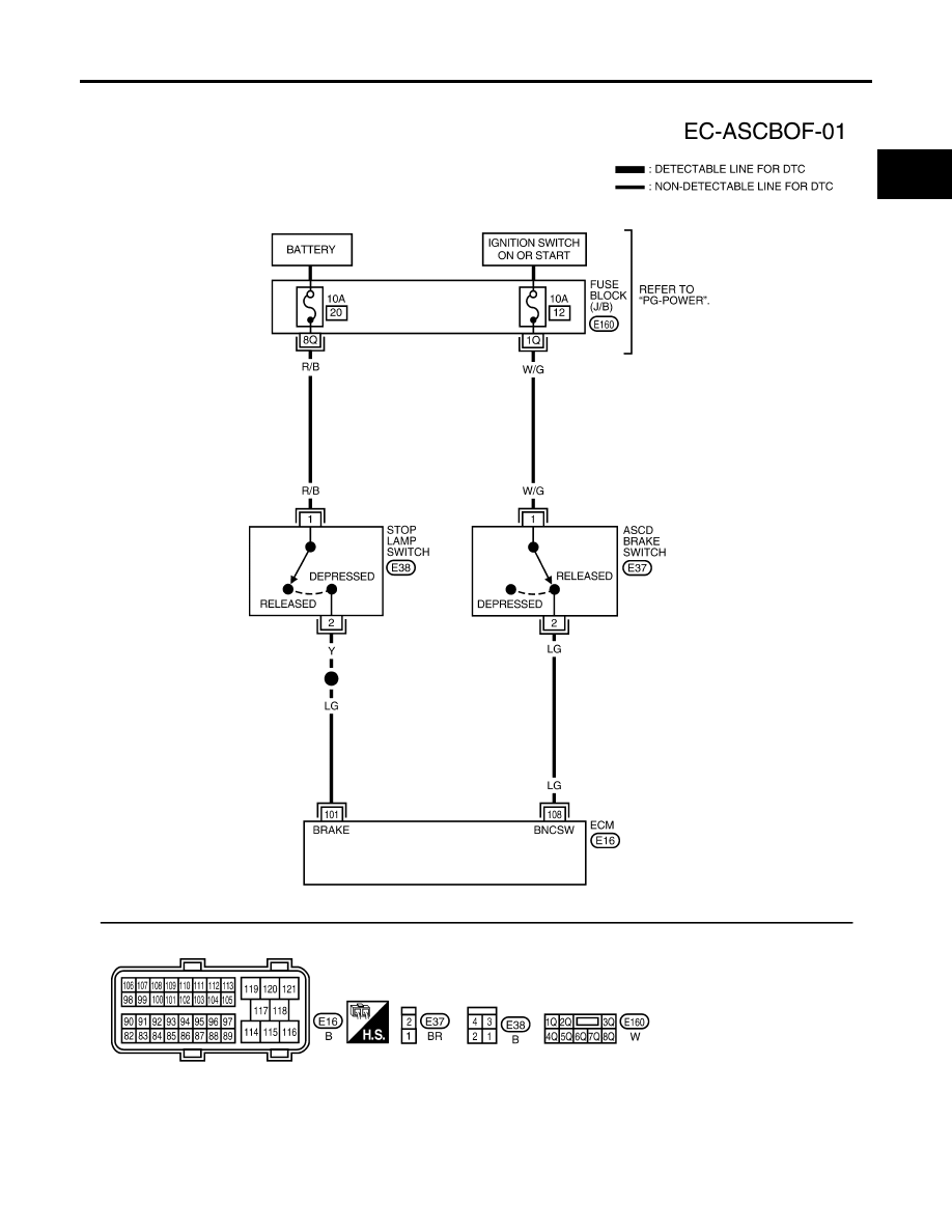
ASCD BRAKE SWITCH
EC-619
C
D
E
F
G
H
I
J
K
L
M
A
EC
2007 Pathfinder
Wiring Diagram
UBS00KIR
BBWA1990E
|
|
|
ASCD BRAKE SWITCH EC-619 C D E F G H I J K L M A EC 2007 Pathfinder Wiring Diagram UBS00KIR BBWA1990E |