Nissan Pathfinder (2007 year). Manual - part 217


  Index      Manuals     Nissan Pathfinder (2007 year) - Service and Repair Manual


Search            copyright infringement  


Content      ..     215      216      217      218     ..


Nissan Pathfinder (2007 year). Manual - part 217


DTC P2138 APP SENSOR

EC-603

C

D

E

F

G

H

I

J

K

L

M

A

EC

2007 Pathfinder

2. 

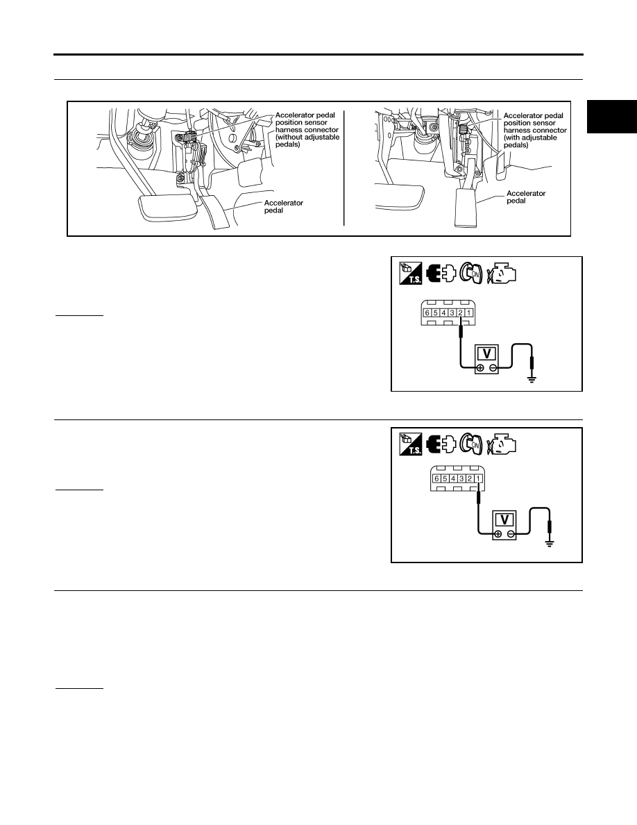
CHECK APP SENSOR 1 POWER SUPPLY CIRCUIT

1.

Disconnect accelerator pedal position (APP) sensor harness connector.

2.

Turn ignition switch ON.

3.

Check voltage between APP sensor terminals 2 and ground with
CONSULT-II or tester.

OK or NG

OK

>> GO TO 3.

NG

>> Repair open circuit or short to ground or short to power

in harness or connectors.

3. 

CHECK APP SENSOR 2 POWER SUPPLY CIRCUIT-I

Check voltage between APP sensor terminal 1 and ground with
CONSULT-II or tester. 

1.

OK or NG

OK

>> GO TO 8.

NG

>> GO TO 4.

4. 

CHECK APP SENSOR 2 POWER SUPPLY CIRCUIT-II

1.

Turn ignition switch OFF.

2.

Disconnect ECM harness connector.

3.

Check harness continuity between APP sensor terminal 1 and ECM terminal 91.
Refer to wiring diagram.

OK or NG

OK

>> GO TO 5.

NG

>> Repair open circuit.

Voltage: Approximately 5V

BBIA0556E

PBIB2608E

Voltage: Approximately 5V

PBIB2611E

Continuity should exist.

EC-604

DTC P2138 APP SENSOR

2007 Pathfinder

5. 

CHECK APP SENSOR 2 POWER SUPPLY CIRCUIT-III

Check harness for short to power and short to ground, between the following terminals.

OK or NG

OK

>> GO TO 6.

NG

>> Repair open circuit or short to ground or short to power in harness or connectors.

6. 

CHECK THROTTLE POSITION SENSOR

Refer to 

EC-341, "Component Inspection"

  .

OK or NG

OK

>> GO TO 12.

NG

>> GO TO 7.

7. 

REPLACE ELECTRIC THROTTLE CONTROL ACTUATOR

1.

Replace electric throttle control actuator.

2.

Perfor

EC-77, "Throttle Valve Closed Position Learning"

  .

3.

Perfor

EC-77, "Idle Air Volume Learning"

  .

>> INSPECTION END

8. 

CHECK APP SENSOR GROUND CIRCUIT FOR OPEN AND SHORT

1.

Turn ignition switch OFF.

2.

Disconnect ECM harness connector.

3.

Check harness continuity between APP sensor terminals 4 and ECM terminal 82, APP sensor terminal 5
and ECM terminal 83.
Refer to Wiring Diagram.

4.

Also check harness for short to ground and short to power.

OK or NG

OK

>> GO TO 9.

NG

>> Repair open circuit or short to ground or short to power in harness or connectors.

9. 

CHECK APP SENSOR INPUT SIGNAL CIRCUIT FOR OPEN AND SHORT

1.

Check harness continuity between ECM terminal 106 and APP sensor terminal 3, ECM terminal 98 and
APP sensor terminal 6.
Refer to Wiring Diagram.

2.

Also check harness for short to ground and short to power.

OK or NG

OK

>> GO TO 10.

NG

>> Repair open circuit or short to ground or short to power in harness or connectors.

ECM terminal

Sensor terminal

Reference Wiring Diagram

91

APP sensor terminal 1

EC-587

47

Electric throttle control actuator terminal 2

EC-594

Continuity should exist.

Continuity should exist.

DTC P2138 APP SENSOR

EC-605

C

D

E

F

G

H

I

J

K

L

M

A

EC

2007 Pathfinder

10. 

CHECK APP SENSOR

Refer to 

EC-605, "Component Inspection"

  .

OK or NG

OK

>> GO TO 12.

NG

>> GO TO 11.

11. 

REPLACE ACCELERATOR PEDAL ASSEMBLY

1.

Replace accelerator pedal assembly.

2.

Perform 

EC-77, "Accelerator Pedal Released Position Learning"

  .

3.

Perform 

EC-77, "Throttle Valve Closed Position Learning"

  .

4.

Perform 

EC-77, "Idle Air Volume Learning"

  .

>> INSPECTION END

12. 

CHECK INTERMITTENT INCIDENT

Refer to 

EC-145, "TROUBLE DIAGNOSIS FOR INTERMITTENT INCIDENT"

  .

>> INSPECTION END

Component Inspection

UBS00KHT

ACCELERATOR PEDAL POSITION SENSOR

1.

Reconnect all harness connectors disconnected.

2.

Turn ignition switch ON.

3.

Check voltage between ECM terminals 106 (APP sensor 1 sig-
nal), 98 (APP sensor 2 signal) and ground under the following
conditions.

4.

If NG, replace accelerator pedal assembly and go to next step.

5.

Perform 

EC-77, "Accelerator Pedal Released Position Learning"

  .

6.

Perform 

EC-77, "Throttle Valve Closed Position Learning"

  .

7.

Perform 

EC-77, "Idle Air Volume Learning"

  .

Removal and Installation

UBS00KHU

ACCELERATOR PEDAL

Refer to 

ACC-3, "ACCELERATOR CONTROL SYSTEM"

  .

Terminal

Accelerator pedal

Voltage

106
 (Accelerator pedal position 
sensor 1)

Fully released

0.65 - 0.87V

Fully depressed

More than 4.3V

98
(Accelerator pedal position 
sensor 2)

Fully released

0.28 - 0.48V

Fully depressed

More than 2.0V

MBIB0023E

EC-606

DTC P2A00, P2A03 A/F SENSOR 1

2007 Pathfinder

DTC P2A00, P2A03 A/F SENSOR 1

PFP:22693

Component Description

UBS00KEG

The air fuel ratio (A/F) sensor 1 is a planar one-cell limit current sen-
sor. The sensor element of the A/F sensor 1 is composed an elec-
trode layer, which transports ions. It has a heater in the element.
The sensor is capable of precise measurement   = 1, but also in the
lean and rich range. Together with its control electronics, the sensor
outputs a clear, continuous signal throughout a wide   range.
The exhaust gas components diffuse through the diffusion layer at
the sensor cell. An electrode layer is applied voltage, and this current
relative oxygen density in lean. Also this current relative hydrocar-
bon density in rich.
Therefore, the A/F sensor 1 is able to indicate air fuel ratio by this
electrode layer of current. In addition, a heater is integrated in the
sensor to ensure the required operating temperature of about 800

°

C

(1,472

°

F).

CONSULT-II Reference Value in Data Monitor Mode

UBS00KEH

Specification data are reference values.

On Board Diagnosis Logic

UBS00KEI

To judge the malfunction, the A/F signal computed by ECM from the A/F sensor 1 signal is monitored not to be
shifted to LEAN side or RICH side.

DTC Confirmation Procedure

UBS00KEJ

NOTE:
If DTC Confirmation Procedure has been previously conducted, always turn ignition switch OFF and wait at
least 10 seconds before conducting the next test.
TESTING CONDITION:
Before performing the following procedure, confirm that battery voltage is more than 11V at idle.

 WITH CONSULT-II

1.

Start engine and warm it up to normal operating temperature.

2.

Turn ignition switch OFF and wait at least 10 seconds.

3.

Turn ignition switch ON and select “SELF-LEARNING CONT” in “WORK SUPPORT” mode with CON-
SULT-II.

PBIB3353E

PBIB3354E

MONITOR ITEM

CONDITION

SPECIFICATION

A/F SEN1 (B1)
A/F SEN1 (B2)

Engine: After warming up

Maintaining engine speed at 
2,000 rpm

Fluctuates around 2.2V

DTC No.

Trouble diagnosis name

DTC detecting condition

Possible Cause

P2A00
2A00
(Bank 1)

Air fuel ratio (A/F) sensor 1 
circuit range/performance

The output voltage computed by ECM from the 
A/F sensor 1 signal is shifted to the lean side 
for a specified period.

The A/F signal computed by ECM from the A/F 
sensor 1 signal is shifted to the rich side for a 
specified period.

A/F sensor 1

A/F sensor 1 heater

Fuel pressure

Fuel injector

Intake air leaks

P2A03
2A03
(Bank 2)

DTC P2A00, P2A03 A/F SENSOR 1

EC-607

C

D

E

F

G

H

I

J

K

L

M

A

EC

2007 Pathfinder

4.

Clear the self-learning coefficient by touching “CLEAR”.

5.

Turn ignition switch OFF and wait at least 10 seconds.

6.

Start engine and keep the engine speed between 3,500 and
4,000 rpm for 1 minute under no load.

7.

Let engine idle for 1 minute.

8.

Keep engine speed between 2,500 and 3,000 rpm for 20 min-
utes.

9.

If 1st trip DTC is detected, go to 

EC-611, "Diagnostic Procedure"

.

 WITH GST

1.

Start engine and warm it up to normal operating temperature.

2.

Turn ignition switch OFF and wait at least 10 seconds.

3.

Disconnect mass air flow sensor harness connector.

4.

Start engine and let it idle for at least 5 seconds.

5.

Stop engine and reconnect mass air flow sensor harness con-
nector.

6.

Select Service $03 with GST and make sure that DTC P0102 is
detected.

7.

Select Service $04 with GST and erase the DTC P0102.

8.

Start engine and keep the engine speed between 3,500 and
4,000 rpm for 1 minute under no load.

9.

Let engine idle for 1 minute.

10. Keep engine speed between 2,500 and 3,000 rpm for 20 min-

utes.

11. Select Service $07 with GST.

If 1st trip DTC is detected, go to 

EC-611, "Diagnostic Procedure"

 .

SEF968Y

BBIA0541E

EC-608

DTC P2A00, P2A03 A/F SENSOR 1

2007 Pathfinder

Wiring Diagram 

UBS00KEK

BANK 1

BBWA2811E

DTC P2A00, P2A03 A/F SENSOR 1

EC-609

C

D

E

F

G

H

I

J

K

L

M

A

EC

2007 Pathfinder

Specification data are reference values and are measured between each terminal and ground.
Pulse signal is measured by CONSULT-II.

CAUTION:

Do not use ECM ground terminals when measuring input/output voltage. Doing so may result in dam-
age to the ECM's transistor. Use a ground other than ECM terminals, such as the ground.

: Average voltage for pulse signal (Actual pulse signal can be confirmed by oscilloscope.)

TERMI-

NAL 

NO.

WIRE 

COLOR

ITEM

CONDITION

DATA (DC Voltage)

2

G

A/F sensor 1 heater (Bank 1)

[Engine is running]

Warm-up condition

Idle speed
(More than 140 seconds after starting 
engine)

Approximately 2.9 - 8.8V

35

O

A/F sensor 1 (Bank 1)

[Engine is running]

Warm-up condition

Engine speed: 2,000 rpm

Approximately 1.8V
Output voltage varies with air 
fuel ratio.

56

LG

A/F sensor 1 (Bank 1)

[Ignition switch: ON]

Approximately 2.2V

PBIA8148J

EC-610

DTC P2A00, P2A03 A/F SENSOR 1

2007 Pathfinder

BANK 2

BBWA2812E


Content      ..     215      216      217      218     ..