Nissan Pathfinder (2007 year). Manual - part 161
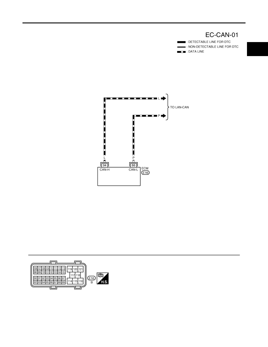
DTC U1000, U1001 CAN COMMUNICATION LINE
EC-155
C
D
E
F
G
H
I
J
K
L
M
A
EC
2007 Pathfinder
Wiring Diagram
UBS00K4S
BBWA2359E
|
|
|
DTC U1000, U1001 CAN COMMUNICATION LINE EC-155 C D E F G H I J K L M A EC 2007 Pathfinder Wiring Diagram UBS00K4S BBWA2359E |