Index Manuals Nissan Pathfinder (2007 year) - Service and Repair Manual
Search copyright infringement
Content .. 137 138 139 140 ..
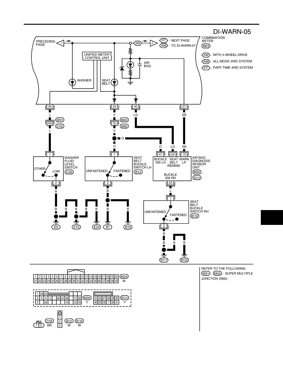
Nissan Pathfinder (2007 year). Manual - part 139
WARNING LAMPS
DI-35
C
D
E
F
G
H
I
J
L
M
A
B
DI
2007 Pathfinder
WKWA5303E