Nissan Pathfinder (2007 year). Manual - part 137


  Index      Manuals     Nissan Pathfinder (2007 year) - Service and Repair Manual


Search            copyright infringement  


Content      ..     135      136      137      138     ..


Nissan Pathfinder (2007 year). Manual - part 137


COMBINATION METERS

DI-19

C

D

E

F

G

H

I

J

L

M

A

B

DI

2007 Pathfinder

3. 

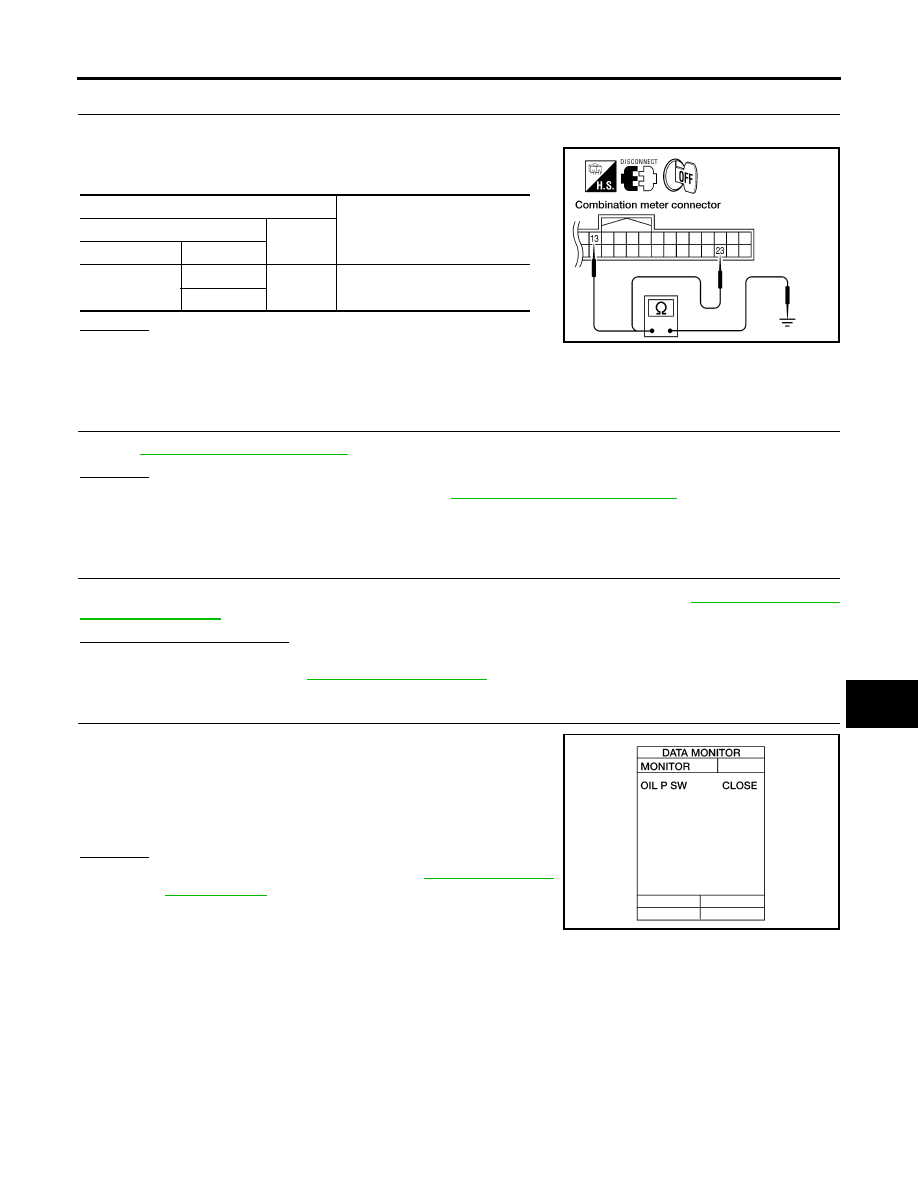
CHECK GROUND CIRCUIT

1.

Turn ignition switch OFF.

2.

Check continuity between combination meter harness connector
terminals and ground.

OK or NG

OK

>> Inspection End.

NG

>> Repair harness or connector.

Vehicle Speed Signal Inspection

EKS00FY7

1. 

CHECK ABS ACTUATOR AND ELECTRIC UNIT (CONTROL UNIT) SELF-DIAGNOSIS

Refer to 

BRC-29, "SELF-DIAGNOSIS"

 .

OK or NG

OK

>> Replace the combination meter. Refer to 

IP-14, "COMBINATION METER"

 .

NG

>> Perform the "Diagnostic Procedure" for displayed DTC.

Engine Oil Pressure Signal Inspection 

EKS00FY8

1. 

CHECK SELF-DIAGNOSTIC RESULTS OF IPDM E/R

Select "IPDM E/R" on CONSULT-II, and perform self-diagnosis of IPDM E/R. Refer to 

PG-20, "SELF-DIAG-

NOSTIC RESULTS"

 .

Self-diagnostic results content

No malfunction detected>>GO TO 2.
Malfunction detected>>GO TO 

PG-20, "Display Item List"

 .

2. 

CHECK IPDM E/R INPUT SIGNAL

Select "IPDM E/R" on CONSULT-II. Operate ignition switch with "OIL
P SW" of "DATA MONITOR" and check operation status.

OK or NG

OK

>> Replace combination meter. Refer to 

IP-14, "COMBINA-

TION METER"

 .

NG

>> GO TO 3.

Terminals

Continuity

(+)

(–)

Connector

Terminal

M24

13

Ground

Yes

23

WKIA3280E

When ignition switch is in ON 
position (Engine stopped)

: OIL P SW CLOSE

When engine running

: OIL P SW OPEN

LKIA0403E

DI-20

COMBINATION METERS

2007 Pathfinder

3. 

CHECK OIL PRESSURE SWITCH CIRCUIT

1.

Turn ignition switch OFF.

2.

Disconnect IPDM E/R connector E122 and oil pressure switch
connector E208.

3.

Check continuity between IPDM E/R harness connector E122
(A) terminal 42 and oil pressure switch harness connector E208
(B) terminal 1.

OK or NG

OK

>> GO TO 4.

NG

>> Repair harness or connector.

4. 

CHECK OIL PRESSURE SWITCH

Check oil pressure switch. Refer to 

DI-23, "OIL PRESSURE SWITCH CHECK"

 .

OK or NG

OK

>> Replace IPDM E/R. Refer to 

PG-32, "Removal and Installation of IPDM E/R"

 .

NG

>> Replace oil pressure switch.

Water Temperature Signal Inspection 

EKS00FY9

1. 

CHECK ECM SELF-DIAGNOSIS

Perform ECM self-diagnosis. Refer to 

EC-117, "SELF-DIAG RESULTS MODE"

 .

OK or NG

OK

>> Replace the combination meter. Refer to 

IP-14, "COMBINATION METER"

 .

NG

>> Perform "Diagnostic procedure" for displayed DTC.

Engine Speed Signal Inspection 

EKS00FYA

1. 

CHECK ECM SELF-DIAGNOSIS

Perform ECM self-diagnosis. Refer to 

EC-117, "SELF-DIAG RESULTS MODE"

 .

OK or NG

OK

>> Replace the combination meter. Refer to 

IP-14, "COMBINATION METER"

 .

NG

>> Perform "Diagnostic procedure" for displayed DTC.

Fuel Level Sensor Unit Inspection

EKS00FYB

FUEL LEVEL SENSOR UNIT

The following symptoms do not indicate a malfunction.

Depending on vehicle position or driving circumstance, the fuel in the tank shifts and the indication may
fluctuate.

If the vehicle is fueled with the ignition switch ON, the indication will update slowly.

If the vehicle is tilted when the ignition switch is turned ON, fuel in the tank may flow to one direction
resulting in a change of reading.

LOW-FUEL WARNING LAMP

Depending on vehicle posture or driving circumstances, the fuel level in the tank varies, and the warning lamp
ON timing may be changed.

1. 

CHECK SELF-DIAGNOSIS

Perform the combination meter self-diagnosis. Refer to 

DI-11, "SELF-DIAGNOSIS FUNCTION"

 .

OK or NG

OK

>> GO TO 2.

NG

>> Replace the combination meter. Refer to 

IP-14, "COMBINATION METER"

 .

Continuity should exist.

WKIA5607E

COMBINATION METERS

DI-21

C

D

E

F

G

H

I

J

L

M

A

B

DI

2007 Pathfinder

2. 

CHECK HARNESS CONNECTOR

1.

Turn the ignition switch OFF.

2.

Check combination meter and fuel level sensor unit and fuel pump terminals (meter-side and harness-
side) for poor connection.

OK or NG

OK

>> GO TO 3.

NG

>> Repair or replace terminals or connectors.

3. 

CHECK HARNESS CONNECTOR OUTPUT SIGNAL

1.

Disconnect fuel level sensor unit and fuel pump connector.

2.

Turn ignition switch ON.

3.

Check voltage between combination meter harness connector
M24 terminal 9 and ground. 

OK or NG

OK

>> GO TO 4.

NG

>> Replace the combination meter. Refer to 

IP-14, "COM-

BINATION METER"

 .

4. 

CHECK HARNESS FOR OPEN OR SHORT CIRCUIT

1.

Turn the ignition switch OFF.

2.

Disconnect combination meter connector M24.

3.

Check continuity between combination meter harness connector
M24 terminal 9 and fuel level sensor unit and fuel pump harness
connector C5 terminal 2.

4.

Check continuity between fuel level sensor unit and fuel pump
harness connector C5 terminal 2 and ground.

OK or NG

OK

>> GO TO 5.

NG

>> Repair harness or connector.

5. 

CHECK FUEL LEVEL SENSOR CIRCUIT

1.

Check continuity between combination meter harness connector
M24 terminal 4 and fuel level sensor unit and fuel pump harness
connector C5 terminal 5.

2.

Check continuity between fuel level sensor unit and fuel pump
harness connector C5 terminal 5 and ground.

OK or NG

OK

>> GO TO 6.

NG

>> Repair harness or connector.

Battery voltage should exist.

WKIA3287E

Continuity should exist.

Continuity should not exist.

WKIA3288E

Continuity should exist.

Continuity should not exist.

WKIA3289E

DI-22

COMBINATION METERS

2007 Pathfinder

6. 

CHECK FUEL LEVEL SENSOR UNIT

Check the fuel level sensor unit. Refer to 

DI-23, "FUEL LEVEL SENSOR UNIT CHECK"

 .

OK or NG

OK

>> GO TO 7.

NG

>> Replace the fuel level sensor unit. Refer to 

FL-6, "Removal and Installation"

 .

7. 

CHECK INSTALLATION CONDITION

Check fuel level sensor unit installation, and determine whether the float arm interferes or binds with any of the
internal components in the fuel tank.

OK or NG

OK

>> Replace the combination meter. Refer to 

IP-14, "COMBINATION METER"

 .

NG

>> Install the fuel level sensor unit properly.

Fuel Gauge Fluctuates, Indicates Wrong Value, or Varies

EKS00FYC

1. 

CHECK FUEL GAUGE FLUCTUATION

Test drive vehicle to see if gauge fluctuates only during driving or just before or just after stopping.

Does the indication value vary only during driving or just before or just after stopping?

YES

>> The fluctuation may be caused by fuel level change in the fuel tank. Condition is normal.

NO

>> Ask the customer in detail about the situation when the symptom occurs. Refer to 

DI-20, "Fuel

Level Sensor Unit Inspection"

 .

Fuel Gauge Does Not Move to Full-position

EKS00FYD

1. 

CHECK POINTER MOVEMENT TO FULL-POSITION

Does it take a long time for the pointer to move to full-position?

YES or NO

YES

>> GO TO 2.

NO

>> GO TO 3.

2. 

CHECK IGNITION SWITCH POSITION

Was the vehicle fueled with the ignition switch ON?

YES or NO

YES

>> Be sure to fuel the vehicle with the ignition switch OFF. Otherwise, it will take a long time for the

pointer to move to full-position because of the characteristic of the fuel gauge.

NO

>> GO TO 3.

3. 

OBSERVE VEHICLE POSITION

Is the vehicle parked on an incline?

YES or NO

YES

>> Check the fuel level indication with vehicle on a level surface.

NO

>> GO TO 4.

4. 

CHECK POINTER MOVEMENT TO EMPTY-POSITION

During driving, does the fuel gauge move gradually toward empty-position?

YES or NO

YES

>> Check the fuel level sensor unit. Refer to 

DI-23, "FUEL LEVEL SENSOR UNIT CHECK"

 .

NO

>> Check fuel level sensor unit installation, and determine whether the float arm interferes or binds

with any of the internal components in the fuel tank.

COMBINATION METERS

DI-23

C

D

E

F

G

H

I

J

L

M

A

B

DI

2007 Pathfinder

DTC [U1000] CAN Communication Circuit

EKS00FYE

Symptom: Display CAN COMM CIRC [U1000] at the result of self-diagnosis for combination meter.

1. 

CHECK CAN COMMUNICATION

1.

Select "SELF-DIAG RESULTS" mode for "METER" with CONSULT-II.

2.

Print out CONSULT-II screen.

>> Go to "CAN SYSTEM". Refer to 

LAN-44, "TROUBLE DIAGNOSIS"

 .

DTC [B2205] Vehicle Speed Circuit

EKS00FYF

Symptom: Display VEHICLE SPEED CIRC [B2205] at the result of self-diagnosis for combination meter.

1. 

CHECK ABS ACTUATOR AND ELECTRIC UNIT (CONTROL UNIT)

Perform ABS actuator and electric unit (control unit) self-diagnosis. Refer to 

BRC-29, "SELF-DIAGNOSIS"

 .

Are self-diagnosis result items displayed?

YES

>> After checking and repairing the applicable item, perform the ABS actuator and electric unit (con-

trol unit) self-diagnosis again.

NO

>> Replace combination meter. Refer to 

IP-14, "COMBINATION METER"

 .

Electrical Components Inspection

EKS00FYG

FUEL LEVEL SENSOR UNIT CHECK

For removal, refer to 

FL-6, "Removal and Installation"

 .

Check Fuel Level Sensor Unit and Fuel Pump

Check resistance between fuel level sensor unit and fuel pump con-
nector terminals 2 and 5.

*1 and *2: When float rod is in contact with stopper.

OIL PRESSURE SWITCH CHECK

Check continuity between the oil pressure switch and body ground.

Removal and Installation

EKS00FYH

COMBINATION METER

Refer to 

IP-14, "COMBINATION METER"

 .

Terminals

Float position

mm (in)

Resistance 

value 

(Approx.)

2

5

*1

Empty

25.86 (1.02)

81.66

*2

Full

254.6 (10.02)

6.98

LKIA0402E

Condition

Oil pressure

kPa (kg/cm

2

 , psi)

Continuity

Engine stopped

Less than 29 (0.3, 4)

Yes

Engine running

More than 29 (0.3, 4) 

No

ELF0044D

DI-24

COMPASS AND THERMOMETER

2007 Pathfinder

COMPASS AND THERMOMETER

PFP:24835

System Description

EKS00FYI

This unit displays the following items:

Earth magnetism and heading direction of vehicle.

Outside air temperature.

Caution for frozen road surfaces.

OUTSIDE TEMPERATURE DISPLAY
With HomeLink® Universal Transceiver

Push the (N) switch when the ignition switch is in the ON position. The outside temperature will be displayed in

°

F”. To change the indication from “

°

F” to “

°

C”, push and hold the (N) switch for about 3 seconds until the dis-

play begins to flash. Press the (N) switch again to toggle between “

°

F” and “

°

C”.

Without HomeLink® Universal Transceiver

Push the mode switch when the ignition switch is in the ON position. The outside temperature will be displayed
in “

°

F”. To change the indication from “

°

F” to “

°

C”, push and hold the mode switch for about 5 seconds until the

display begins to flash. Press the mode switch again to toggle between “

°

F” and “

°

C”.

DIRECTION DISPLAY

Push the mode or (N) switch when the ignition switch is in the ON position. The direction will be displayed.

WKIA4889E

COMPASS AND THERMOMETER

DI-25

C

D

E

F

G

H

I

J

L

M

A

B

DI

2007 Pathfinder

Wiring Diagram — COMPAS —

EKS00FYJ

WITHOUT HOMELINK® UNIVERSAL TRANSCEIVER

WKWA2048E

DI-26

COMPASS AND THERMOMETER

2007 Pathfinder

WITH HOMELINK® UNIVERSAL TRANSCEIVER

WKWA2049E


Content      ..     135      136      137      138     ..