Nissan Pathfinder (2007 year). Manual - part 131


  Index      Manuals     Nissan Pathfinder (2007 year) - Service and Repair Manual


Search            copyright infringement  


Content      ..     129      130      131      132     ..


Nissan Pathfinder (2007 year). Manual - part 131


G SENSOR

BRC-133

[HDC/HSA/VDC/TCS/ABS]

C

D

E

G

H

I

J

K

L

M

A

B

BRC

2007 Pathfinder

G SENSOR

PFP:47930

Removal and Installation

EFS0067R

REMOVAL

1.

Remove center console. Refer to 

IP-16, "CENTER CONSOLE"

 .

2.

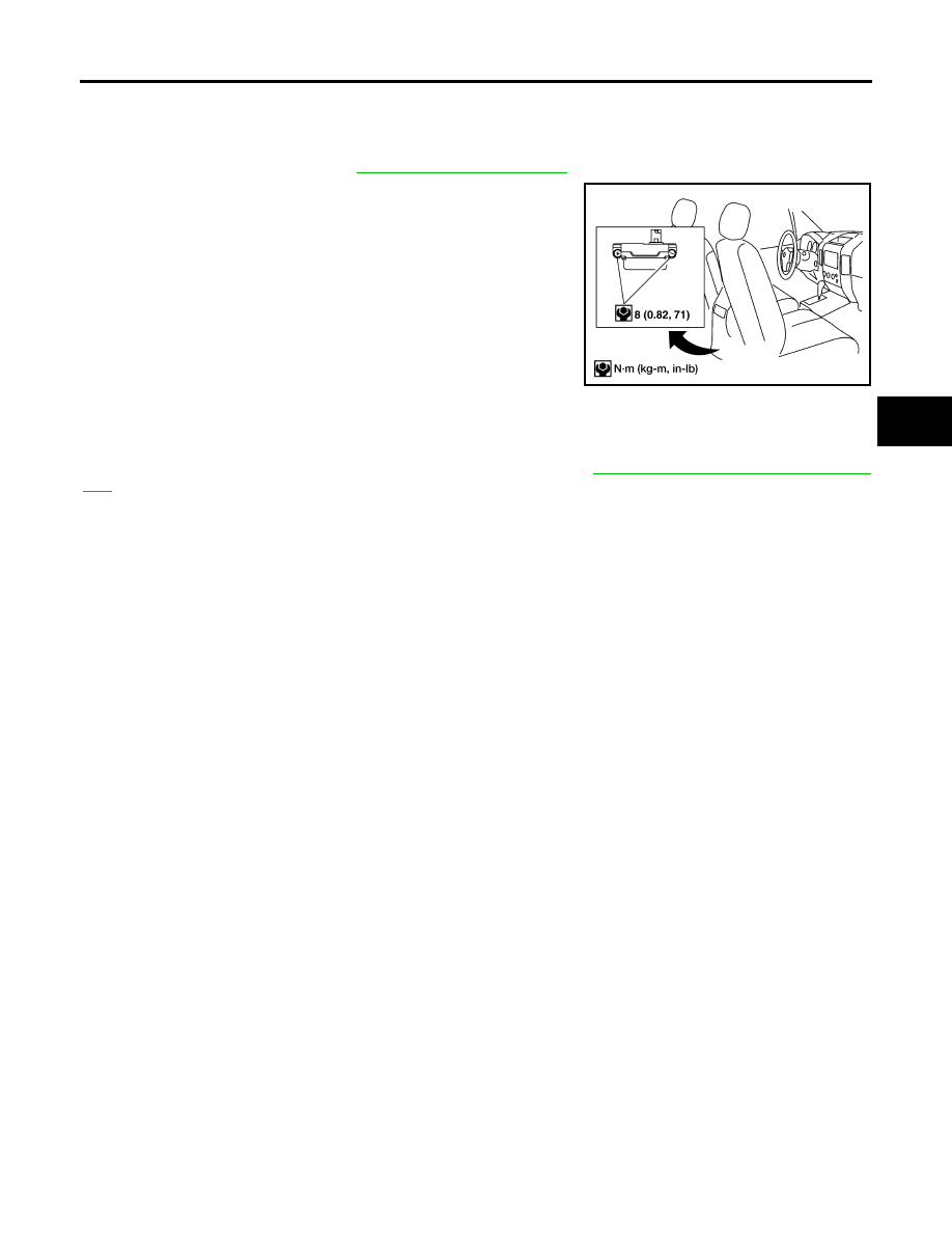
Remove yaw rate/side/decel G sensor nuts as shown.

The location of the sensor is the same for all models.

CAUTION:

Do not use power tools to remove or install yaw rate/side/
decel G sensor.

Do not drop or strike the yaw rate/side/decel G sensor.

3.

Disconnect harness connector and remove the yaw rate/side/
decel G sensor.

INSTALLATION

Installation is in the reverse order of removal.

NOTE:
After performing the above work, calibrate the decel G sensor. Refer to 

BRC-126, "Calibration of Decel G Sen-

sor"

 .

WFIA0230E

BRC-134

[HDC/HSA/VDC/TCS/ABS]

G SENSOR

2007 Pathfinder

CO-1

ENGINE COOLING SYSTEM

B  ENGINE

CONTENTS

C

D

E

F

G

H

I

J

K

L

M

SECTION 

CO

A

CO

2007 Pathfinder

PRECAUTIONS .......................................................... 2

Precautions for Liquid Gasket  .................................. 2

REMOVAL OF LIQUID GASKET SEALING .......... 2
LIQUID GASKET APPLICATION PROCEDURE 

..... 2

PREPARATION ........................................................... 3

Special Service Tools  ............................................... 3
Commercial Service Tools ........................................ 4

OVERHEATING CAUSE ANALYSIS .......................... 5

Troubleshooting Chart .............................................. 5

COOLING SYSTEM .................................................... 7

Cooling Circuit .......................................................... 7
System Chart  ........................................................... 8

ENGINE COOLANT .................................................... 9

System Check  .......................................................... 9

CHECKING COOLING SYSTEM HOSES  ............ 9
CHECKING RESERVOIR LEVEL ......................... 9
CHECKING COOLING SYSTEM FOR LEAKS ..... 9
CHECKING RESERVOIR CAP ........................... 10
CHECKING RADIATOR  ...................................... 10

Changing Engine Coolant  ...................................... 10

DRAINING ENGINE COOLANT  ......................... 10
REFILLING ENGINE COOLANT  .........................11
FLUSHING COOLING SYSTEM ......................... 13

RADIATOR ................................................................ 14

Removal and Installation  ........................................ 14

REMOVAL ........................................................... 14
INSTALLATION ................................................... 16
INSPECTION AFTER INSTALLATION  ............... 16

ENGINE COOLING FAN  .......................................... 17

Removal and Installation (Crankshaft driven type) 

... 17

REMOVAL ........................................................... 17
INSPECTION AFTER REMOVAL  ....................... 17
INSTALLATION ................................................... 17
INSPECTION AFTER INSTALLATION ................ 18

Removal and Installation (Motor driven type)  ......... 18

REMOVAL ........................................................... 18
INSTALLATION ................................................... 18

WATER PUMP  .......................................................... 19

Removal and Installation  ........................................ 19

REMOVAL ........................................................... 19
INSPECTION AFTER REMOVAL  ....................... 21
INSTALLATION ................................................... 21
INSPECTION AFTER INSTALLATION ................ 22

WATER INLET AND THERMOSTAT ASSEMBLY .... 24

Removal and Installation  ........................................ 24

REMOVAL ........................................................... 24
INSPECTION AFTER REMOVAL  ....................... 24
INSTALLATION ................................................... 25
INSPECTION AFTER INSTALLATION ................ 25

WATER OUTLET AND WATER PIPING ................... 26

Removal and Installation  ........................................ 26

REMOVAL ........................................................... 26
INSTALLATION ................................................... 26
INSPECTION AFTER INSTALLATION ................ 26

SERVICE DATA AND SPECIFICATIONS (SDS)  ...... 28

Standard and Limit .................................................. 28

ENGINE COOLANT CAPACITY (APPROXI-
MATE) .................................................................. 28
RADIATOR .......................................................... 28
THERMOSTAT .................................................... 28

CO-2

PRECAUTIONS

2007 Pathfinder

PRECAUTIONS

PFP:00001

Precautions for Liquid Gasket

EBS00QCQ

REMOVAL OF LIQUID GASKET SEALING

After removing nuts and bolts, separate the mating surface, using Tool and remove old liquid gasket seal-
ing.    

CAUTION:

Be careful not to damage the mating surfaces.

Tap Tool to insert it, and then slide it by tapping on the side as
shown.

In areas where Tool is difficult to use, use plastic hammer to
lightly tap the parts, to remove it.

CAUTION:

If for some unavoidable reason suitable tool such as screw-
driver is used, be careful not to damage the mating sur-
faces.

LIQUID GASKET APPLICATION PROCEDURE

1.

Remove old liquid gasket adhering to the liquid gasket applica-
tion surface and the mating surface, Using scraper.

Remove liquid gasket completely from the groove of the liquid
gasket application surface, bolts, and bolt holes.

2.

Thoroughly clean the mating surfaces and remove adhering
moisture, grease and foreign materials.

3.

Attach liquid gasket tube to Tool.

Use Genuine RTV Silicone Sealant or equivalent. Refer to

GI-47, "Recommended Chemical Products and Sealants"

 .

4.

Apply liquid gasket without breaks to the specified location with
the specified dimensions.

If there is a groove for the liquid gasket application, apply liq-
uid gasket to the groove.

As for the bolt holes, normally apply liquid gasket inside the
holes. Occasionally, it should be applied outside the holes.
Make sure to read the text of service manual.

Within five minutes of liquid gasket application, install the mat-
ing component.

If liquid gasket protrudes, wipe it off immediately.

Do not retighten nuts or bolts after the installation.

After 30 minutes or more have passed from the installation, fill
engine oil and engine coolant.

CAUTION:

If there are specific instructions in this manual, observe them.

Tool number

: KV10111100 (J-37228)

WBIA0566E

PBIC0003E

Tool number

: WS39930000 (

)

WBIA0567E

SEM159F

PREPARATION

CO-3

C

D

E

F

G

H

I

J

K

L

M

A

CO

2007 Pathfinder

PREPARATION

PFP:00002

Special Service Tools

EBS00QCR

The actual shapes of Kent-Moore tools may differ from those of special service tools illustrated here.

Tool number
(Kent-Moore No.)
Tool name

Description

EG17650301
(J-33984-A)
Radiator cap tester adapter

Adapting radiator cap tester to radiator cap 
and radiator filler neck
a: 28 (1.10) dia.
b: 31.4 (1.236) dia.
c: 41.3 (1.626) dia.
Unit: mm (in)

KV10111100
(J-37228)
Seal cutter

Removing chain tensioner cover and water 
pump cover

WS39930000
(

)

Tube presser

Pressing the tube of liquid gasket

KV991J0070
(J-45695)
Coolant refill tool

Filling cooling system

KV991J0010
(J-23688)
Engine coolant refractometer

Checking concentration of ethylene glycol in 
engine coolant

S-NT564

NT046

S-NT052

LMA053

WBIA0539E

CO-4

PREPARATION

2007 Pathfinder

Commercial Service Tools

EBS00QCS

Tool name

Description

Power tool

Loosening nuts and bolts

Radiator cap tester

Checking radiator and radiator cap

PBIC0190E

PBIC1982E

OVERHEATING CAUSE ANALYSIS

CO-5

C

D

E

F

G

H

I

J

K

L

M

A

CO

2007 Pathfinder

OVERHEATING CAUSE ANALYSIS

PFP:00012

Troubleshooting Chart

EBS00QCT

Symptom

Check items

Cooling sys-
tem parts 
malfunction

Poor heat transfer

Water pump malfunction

Worn or loose drive belt

Thermostat stuck closed

Damaged fins

Dust contamination or 
paper clogging

Clogged radiator cooling 
tube

Excess foreign material 
(rust, dirt, sand, etc.)

Reduced air flow

Cooling fan does not oper-
ate

Fan assembly

High resistance to fan rota-
tion

Damaged fan blades

Damaged radiator shroud

Improper engine coolant 
mixture ratio

Poor engine coolant quality

Engine coolant viscosity

Insufficient engine coolant

Engine coolant leaks

 Cooling hose

Loose clamp

Cracked hose

Heater pump

Physical damage

Water pump

Poor sealing

Radiator cap

Loose

Poor sealing

Radiator

O-ring for damage, deterio-
ration or improper fitting

Cracked radiator tank

Cracked radiator core

Reservoir tank

Cracked reservoir tank

Overflowing reservoir tank

Exhaust gas leaks into 
cooling system

Cylinder head deterioration

Cylinder head gasket dete-
rioration

CO-6

OVERHEATING CAUSE ANALYSIS

2007 Pathfinder

Except cool-
ing system 
parts mal-
function

Overload on engine

Abusive driving

High engine rpm under no 
load

Driving in low gear for 
extended time

Driving at extremely high 
speed

Powertrain system mal-
function

Installed improper size 
wheels and tires

Dragging brakes

Improper ignition timing

Blocked or restricted air 
flow 

Blocked bumper

Blocked radiator grille

Installed car brassiere

Mud contamination or 
paper clogging

Blocked radiator

Blocked condenser

Blocked air flow

Installed large fog lamp

Symptom

Check items


Content      ..     129      130      131      132     ..