Nissan Pathfinder (2007 year). Manual - part 121


  Index      Manuals     Nissan Pathfinder (2007 year) - Service and Repair Manual


Search            copyright infringement  


Content      ..     119      120      121      122     ..


Nissan Pathfinder (2007 year). Manual - part 121


TROUBLE DIAGNOSES FOR SYMPTOMS

BRC-53

[VDC/TCS/ABS]

C

D

E

G

H

I

J

K

L

M

A

B

BRC

2007 Pathfinder

Unexpected Pedal Action

EFS0065O

1. 

CHECK WARNING LAMP ACTIVATION

Make sure warning lamp remains off while driving.

OK or NG

OK

>> GO TO 2.

NG

>> Carry out self-diagnosis. Refer to 

BRC-29, "SELF-DIAGNOSIS"

 .

2. 

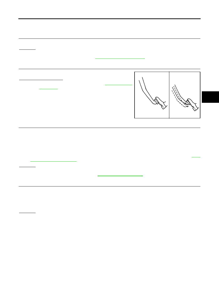
CHECK BRAKE PEDAL STROKE

Check brake pedal stroke.

Is pedal stroke excessive?

YES

>> Perform Basic Inspection. Refer to 

BRC-24, "Basic

Inspection"

 .

NO

>> GO TO 3.

3. 

CHECK CONNECTOR AND BRAKING PERFORMANCE

1.

Disable ABS by disconnecting ABS actuator and electric unit (control unit) connector.

2.

Drive vehicle and check brake operation.

NOTE:

Stopping distance may be longer than vehicles without ABS when road condition is slippery.

Driving the vehicle with the ABS actuator and electric unit (control unit) disconnected may induce DTCs
in electrical control units using CAN communication. After the inspection, clear all DTCs. Refer to 

LAN-

7, "TROUBLE DIAGNOSIS"

 .

OK or NG

OK

>> GO TO 4.

NG

>> Perform Basic Inspection. Refer to 

BRC-24, "Basic Inspection"

 .

4. 

CHECK WHEEL SENSORS

Check the following.

Wheel sensor mounting for looseness

Wheel sensors for physical damage

Wheel sensor connectors for terminal damage or loose connections

OK or NG

OK

>> Check ABS actuator and electric unit (control unit) connector terminals for deformation, discon-

nection, looseness or damage. Reconnect ABS actuator and electric unit (control unit) harness
connector. Then retest.

NG

>> Repair or replace as necessary.

SBR540A

BRC-54

[VDC/TCS/ABS]

TROUBLE DIAGNOSES FOR SYMPTOMS

2007 Pathfinder

Long Stopping Distance

EFS0065P

1. 

CHECK BASE BRAKING SYSTEM PERFORMANCE

1.

Disable ABS by disconnecting ABS actuator and electric unit (control unit) connector.

2.

Drive vehicle and check brake operation.

NOTE:

Stopping distance may be longer than vehicles without ABS when road condition is slippery.

Driving the vehicle with the ABS actuator and electric unit (control unit) disconnected may induce DTCs
in electrical control units using CAN communication. After the inspection, clear all DTCs. Refer to 

LAN-

7, "TROUBLE DIAGNOSIS"

 .

OK or NG

OK

>> Go to 

BRC-52, "ABS Works Frequently"

 .

NG

>> Perform Basic Inspection. Refer to 

BRC-24, "Basic Inspection"

 .

ABS Does Not Work

EFS0065Q

CAUTION:

The ABS does not operate when the vehicle speed is 10 km/h (6 MPH) or less.

1. 

CHECK WARNING LAMP ACTIVATION

Turn ignition switch ON and check for warning lamp activation.

Warning lamp should activate for approximately 2 seconds after turning the ignition switch ON.

OK or NG

OK

>> Carry out self-diagnosis. Refer to 

BRC-29, "SELF-DIAGNOSIS"

 .

NG

>> Go to 

BRC-55, "ABS Warning Lamp Does Not Come On When Ignition Switch Is Turned On"

 .

Pedal Vibration or ABS Operation Noise

EFS0065R

NOTE:
During ABS activation, pedal vibration may be felt and a noise may be heard. This is normal and does not indi-
cate a malfunction.

1. 

CHECK SYMPTOM

1.

Apply brake.

2.

Start engine.

Does the symptom occur only when engine is started?

YES

>> Carry out self-diagnosis. Refer to 

BRC-29, "SELF-DIAGNOSIS"

 .

NO

>> GO TO 2.

2. 

RECHECK SYMPTOM

Does the symptom occur only when electrical equipment switches (such as headlamps) are turned on?

YES

>> Check for radio, antenna or related wiring that is routed too close to the ABS actuator and electric

unit (control unit) and reroute as necessary.

NO

>> Go to 

BRC-52, "ABS Works Frequently"

 .

TROUBLE DIAGNOSES FOR SYMPTOMS

BRC-55

[VDC/TCS/ABS]

C

D

E

G

H

I

J

K

L

M

A

B

BRC

2007 Pathfinder

ABS Warning Lamp Does Not Come On When Ignition Switch Is Turned On

EFS0065S

1. 

CHECK ABS ACTUATOR AND ELECTRIC UNIT (CONTROL UNIT) FUSES

Check 40A fusible link n  and 30A fusible link l  for ABS actuator and electric unit (control unit). For fusible link
layout, refer to 

PG-4, "POWER SUPPLY ROUTING CIRCUIT"

 .

OK or NG

OK

>> GO TO 2.

NG

>> If fusible link is blown, be sure to eliminate cause of problem before replacing.

2. 

CHECK ABS ACTUATOR AND ELECTRIC UNIT (CONTROL UNIT) POWER SUPPLY CIRCUITS

1.

Disconnect ABS actuator and electric unit (control unit) connec-
tor.

2.

Check voltage between ABS actuator and electric unit (control
unit) connector terminal 1 and ground and terminal 32 and
ground.

Does battery voltage exist?

YES

>> GO TO 3.

NO

>> Repair harness or connectors between fusible link and

ABS actuator and electric unit (control unit).

3. 

CHECK ABS ACTUATOR AND ELECTRIC UNIT (CONTROL UNIT) GROUND CIRCUIT

Check continuity between ABS actuator and electric unit (control
unit) connector terminal 16 and ground and terminal 47 and ground.

Does continuity exist?

YES

>> Replace ABS actuator and electric unit (control unit).

Refer to 

BRC-61, "Removal and Installation"

 .

NO

>> Repair harness or connectors between ABS actuator

and electric unit (control unit) and ground.

ABS Warning Lamp Stays On When Ignition Switch Is Turned On

EFS0065T

1. 

CARRY OUT SELF-DIAGNOSIS

Carry out self-diagnosis. Refer to 

BRC-29, "SELF-DIAGNOSIS"

 .

Are malfunctions detected in self-diagnosis?

YES

>> Refer to 

BRC-30, "Display Item List"

 .

NO

>> Refer to 

DI-30, "WARNING LAMPS"

 .

WFIA0199E

WFIA0196E

BRC-56

[VDC/TCS/ABS]

TROUBLE DIAGNOSES FOR SYMPTOMS

2007 Pathfinder

Vehicle Jerks During TCS/VDC Activation

EFS0065U

1. 

ABS ACTUATOR AND ELECTRIC UNIT (CONTROL UNIT) SELF-DIAGNOSIS

Perform ABS actuator and electric unit (control unit) self-diagnosis.

Are self-diagnosis result items displayed?

YES

>> After checking and repairing the applicable item, perform the ABS actuator and electric unit (con-

trol unit) self-diagnosis again.

NO

>> GO TO 2.

2. 

ENGINE SPEED SIGNAL INSPECTION

Perform data monitor with CONSULT-II for the ABS actuator and electric unit (control unit).

Is the engine speed at idle 400 rpm or higher?

YES

>> GO TO 4.

NO

>> GO TO 3.

3. 

ECM SELF-DIAGNOSIS

Perform ECM self-diagnosis.

Are self-diagnosis result items displayed?

YES

>> After checking and repairing the applicable item, perform the ECM self-diagnosis again.

NO

>> GO TO 4.

4. 

TCM SELF-DIAGNOSIS

Perform TCM self-diagnosis.

Are self-diagnosis result items displayed?

YES

>> After checking and repairing the applicable item, perform the TCM self-diagnosis again.

NO

>> GO TO 5.

5. 

CONNECTOR INSPECTION

Disconnect the ABS actuator and electric unit (control unit) connector and the ECM connectors and check the
terminals for deformation, disconnection, looseness or damage.

OK or NG

OK

>> GO TO 6.

NG

>> Repair or replace as necessary.

6. 

CAN COMMUNICATION INSPECTION

Check the CAN communication system. Refer to 

BRC-50, "CAN Communication System Inspection"

 .

OK or NG

OK

>> Inspection End.

NG

>> Refer to 

LAN-7, "TROUBLE DIAGNOSIS"

 .

ON-VEHICLE SERVICE

BRC-57

[VDC/TCS/ABS]

C

D

E

G

H

I

J

K

L

M

A

B

BRC

2007 Pathfinder

ON-VEHICLE SERVICE

PFP:00000

Adjustment of Steering Angle Sensor Neutral Position

EFS0065V

After removing/installing or replacing ABS actuator and electric unit (control unit), steering angle sensor, steer-
ing and suspension components which affect wheel alignment or after adjusting wheel alignment, be sure to
adjust neutral position of steering angle sensor before running vehicle.

 WITH CONSULT-II

1.

Stop vehicle with front wheels in straight-ahead position.

2.

Connect CONSULT-II and CONSULT-II CONVERTER to data
link connector on vehicle, and turn ignition switch ON (do not
start engine).

3.

Touch “START (NISSAN BASED VHCL)”, “ABS”, “WORK SUP-
PORT” and “ST ANGLE SENSOR ADJUSTMENT” on CON-
SULT-II screen in this order.

4.

Touch “START”.

CAUTION:

Do not touch steering wheel while adjusting steering angle
sensor.

5.

After approximately 10 seconds, touch “END”. (After approxi-
mately 60 seconds, it ends automatically.)

6.

Turn ignition switch OFF, then turn it ON again.

CAUTION:

Do not touch steering wheel while adjusting steering angle
sensor.

7.

Run vehicle with front wheels in straight-ahead position, then
stop.

8.

Select “DATA MONITOR”, “SELECTION FROM MENU”, and “STR ANGLE SIG” on CONSULT-II screen.
Then check that “STR ANGLE SIG” is within 0

±

3.5 deg. If value is more than specification, repeat steps 3

to 7.

9.

Erase memory of ABS actuator and electric unit (control unit) and ECM.

10. Turn ignition switch to OFF.

 WITHOUT CONSULT-II

Set the steering wheel in a straight forward position and drive the vehicle at 10 mph (15 km/h) or more for 10
minutes. When the procedure is complete, the SLIP indicator lamp and VDC OFF indicator lamp will turn off.

Calibration of Decel G Sensor

EFS0065W

After removing/installing or replacing ABS actuator and electric unit (control unit), yaw rate/side/decel G sen-
sor, steering and suspension components which affect wheel alignment or after adjusting wheel alignment, be
sure to calibrate the decel G sensor before running vehicle.

NOTE:
Calibration of decel G sensor requires CONSULT-II.

1.

Stop vehicle with front wheels in straight-ahead position.

CAUTION:

The work should be done on a level area with an unloaded vehicle.

Keep all the tires inflated to the correct pressures. Adjust the tire pressure to the specified pres-
sure value.

2.

Connect CONSULT-II with CONSULT-II CONVERTER to data link connector on vehicle, and turn ignition
switch ON (do not start engine).

BBIA0538E

WFIA0239E

BRC-58

[VDC/TCS/ABS]

ON-VEHICLE SERVICE

2007 Pathfinder

CAUTION:

If CONSULT-II is used with no connection of CONSULT-II CONVERTER, malfunctions might be
detected in self-diagnosis depending on control unit which carries out CAN communication.

3.

Touch “START (NISSAN BASED VHCL)”, "ABS", "WORK SUPPORT" and "DECEL G SEN CALIBRA-
TION" on CONSULT-II screen in this order. Refer to 

BRC-29, "CONSULT-II START PROCEDURE"

 .

4.

Touch "START".

CAUTION:

Set vehicle as shown in the display.

5.

After approximately 10 seconds, touch "END". (After approxi-
mately 60 seconds, it ends automatically.)

6.

Turn ignition switch OFF, then turn it ON again.

CAUTION:

Be sure to carry out above operation.

7.

Run vehicle with front wheels in straight-ahead position, then
stop.

8.

Select "DATA MONITOR", "SELECTION FROM MENU", and
"DECEL G SEN" on CONSULT-II screen. Then check that "DECEL G SEN" is within 

±

0.08G. If value is

more than specification, repeat steps 3 to 7.

9.

Erase memory of ABS actuator and electric unit (control unit) and ECM.

10. Turn ignition switch to OFF.

SFIA1162E

WHEEL SENSORS

BRC-59

[VDC/TCS/ABS]

C

D

E

G

H

I

J

K

L

M

A

B

BRC

2007 Pathfinder

WHEEL SENSORS

PFP:47910

Removal and Installation

EFS0065X

REMOVAL

1.

Remove wheel and tire using power tool.

2.

Remove wheel sensor mounting screw.

NOTE:

When removing front wheel sensor, first remove the disc rotor to gain access to the front wheel sensor
mounting bolt. Refer to 

BR-25, "Removal and Installation of Brake Caliper and Disc Rotor"

 .

When removing rear wheel sensor, first remove spare tire.

3.

Pull out the wheel sensor, being careful to turn it as little as possible.

CAUTION:

Be careful not to damage sensor edge and sensor rotor teeth.

Do not pull on the sensor harness.

4.

Disconnect wheel sensor harness electrical connector, then remove harness from mounts.

INSTALLATION

Installation is in the reverse order of removal.  When installing wheel and tire, refer to 

WT-7, "Rotation"

 .

CAUTION:

Inspect wheel sensor O-ring, replace sensor assembly if damaged.

Clean wheel sensor hole and mounting surface with brake cleaner and a lint-free shop rag. Be
careful that dirt and debris do not enter the axle.

NOTE:

Apply a coat of suitable grease to the wheel sensor O-ring and mounting hole.

Tighten wheel sensor bolt to specification.

WFIA0333E

BRC-60

[VDC/TCS/ABS]

SENSOR ROTOR

2007 Pathfinder

SENSOR ROTOR

PFP:47970

Removal and Installation 

EFS0065Y

FRONT

The wheel sensor rotors are built into the wheel hubs and are not removable. If damaged, replace wheel hub
and bearing assembly. Refer to 

FAX-5, "Removal and Installation"

 .

REAR
Removal

1.

Remove side flange from final drive assembly. Refer to 

RFD-12, "Removal and Installation"

 .

CAUTION:

Discard side oil seal.

2.

Using tool and a suitable puller, remove sensor rotor from side flange.

Installation

1.

Install new sensor rotor on side flange using Tools and a press.
Make sure sensor rotor is fully seated.

CAUTION:

Do not reuse the old sensor rotor.

2.

Install side flange to final drive assembly. Refer to 

RFD-12,

"Removal and Installation"

 .

CAUTION:

Do not reuse the side oil seal. The side oil seal must be replaced every time the side flange is
removed from the final drive assembly.

Tool number

: ST30031000 (

)

Tool numbers

A: ST30720000 (J-25405)

B: ST27863000 (

)

C: KV40104710 (

)

WFIA0334E


Content      ..     119      120      121      122     ..