Nissan Pathfinder (2007 year). Manual - part 113


  Index      Manuals     Nissan Pathfinder (2007 year) - Service and Repair Manual


Search            copyright infringement  


Content      ..     111      112      113      114     ..


Nissan Pathfinder (2007 year). Manual - part 113


FRONT DISC BRAKE

BR-25

C

D

E

G

H

I

J

K

L

M

A

B

BR

2007 Pathfinder

CAUTION:

While removing cylinder body never depress brake pedal because piston will pop out. 

It is not necessary to remove bolts on torque member and brake hose except for disassembly or
replacement of cylinder body. In this case, hang cylinder body with a wire so as not to stretch
brake hose.

Do not damage piston boot.

Burnish brake contact surface after refinishing or replacing rotors, after replacing pads, or if a soft
pedal occurs at very low mileage. Refer to 

BR-29, "Brake Burnishing"

 .

Removal and Installation of Brake Pad

EFS0063W

REMOVAL

1.

Remove wheel and tire using power tool.

2.

Remove master cylinder reservoir cap.

3.

Remove lower sliding pin bolt using power tool.

4.

Suspend cylinder body with a wire and remove pad return spring, pads, shim, shim covers, and retainers
from torque member.

INSTALLATION

1.

Apply Molykote M-77 grease between outer brake pad plate and shim, then attach shim and shim covers
to brake pads. Refer to 

MA-11, "RECOMMENDED FLUIDS AND LUBRICANTS"

 .

2.

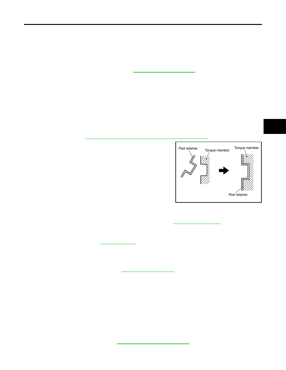
Attach pad retainer to torque member, then install brake pad,
shims and pad return spring.

CAUTION:

When attaching pad retainer, attach it firmly so that it is
flush with torque member, as shown.

3.

Push pistons into cylinder body.

NOTE:
Using a disc brake piston tool (commercial service tool), etc.,
makes it easier to push in piston.

CAUTION:

By pushing in piston, brake fluid returns to master cylinder
reservoir tank. Watch the level of the surface of reservoir tank.

4.

Remove wire then swing cylinder body down over brake pad assemblies.

5.

Install lower sliding pin bolt and tighten to specification. Refer to 

BR-24, "Components"

 .

6.

Check brake for drag.

7.

Inspect fluid level, then install master cylinder reservoir cap.

8.

Install wheel and tire. Refer to 

WT-7, "Rotation"

 .

Removal and Installation of Brake Caliper and Disc Rotor

EFS0063X

REMOVAL

1.

Remove wheel and tire using power tool.

2.

Drain brake fluid as necessary. Refer to 

BR-11, "Drain and Refill"

 .

NOTE:
Do not remove union bolt unless removing cylinder body from vehicle.

3.

Remove union bolt as necessary and torque member bolts, then remove cylinder body from the vehicle.

NOTE:

Position cylinder body aside using suitable wire, as necessary.

When servicing brake caliper, remove sliding pin bolts and caliper from torque member.

4.

Remove torque member.

5.

Remove disc rotor.

INSTALLATION

CAUTION:

Refill with new brake fluid. Refer to 

MA-11, "Fluids and Lubricants"

 . 

Do not reuse drained brake fluid.

PFIA0273E

BR-26

FRONT DISC BRAKE

2007 Pathfinder

1.

Install disc rotor.

2.

Install torque member and tighten to specification. Refer to 

BR-24, "Components"

 .

3.

Install sliding pin bolts, if removed.

4.

Install cylinder body, then tighten sliding pin bolts to the specified
torque. Refer to 

BR-24, "Components"

 .

CAUTION:

When attaching cylinder body to the vehicle, wipe any oil
off knuckle spindle, washers and cylinder body attachment
surfaces.

5.

Install brake hose to cylinder body, if removed, then tighten
union bolt to the specified torque. Refer to 

BR-24, "Compo-

nents"

 .

CAUTION:

Do not reuse copper washers for union bolt.

Attach brake hose to cylinder body together with union
bolt and washers.

6.

Refill with new brake fluid as necessary and bleed air. Refer to 

BR-12, "Bleeding Brake System"

 .

7.

Install wheel and tire. Refer to 

WT-7, "Rotation"

 .

Disassembly and Assembly of Brake Caliper

EFS0063Y

DISASSEMBLY

1.

Remove sliding pin bolt, and then remove the pad, shim, shim cover, and pad retainer from the torque
member.

2.

Remove sliding pins and sliding pin boots from torque member.

3.

Place a wooden block as shown, and blow air from union bolt
mounting hole to remove pistons and piston boots.

CAUTION:

Do not get your fingers caught in piston.

LFIA0239E

LFIA0235E

BRB0032D

FRONT DISC BRAKE

BR-27

C

D

E

G

H

I

J

K

L

M

A

B

BR

2007 Pathfinder

4.

Using a suitable tool, remove piston seal from cylinder body.

CAUTION:

Be careful not to damage cylinder inner wall.

Do not reuse piston seal.

CALIPER INSPECTION
Cylinder Body

CAUTION:

Use new brake fluid for cleaning. Do not use mineral oils such as gasoline or kerosene. Refer to

MA-11, "RECOMMENDED FLUIDS AND LUBRICANTS"

 .

Check inside surface of cylinder for score, rust, wear, damage or foreign materials. If any of the
above conditions are observed, replace cylinder body.

Minor damage from rust or foreign materials may be eliminated by polishing surface with a fine
emery paper. Replace cylinder body if necessary.

Torque Member

Check for wear, cracks, and damage. If damage or deformation is present, replace the affected part.

Piston

Check piston for score, rust, wear, damage or presence of foreign materials. Replace if any of the above con-
ditions are observed. 

CAUTION:

Piston sliding surface is plated, do not polish with emery paper even if rust or foreign materials are
stuck to sliding surface.

Sliding Pins, and Sliding Pin Boots

Check sliding pin and sliding pin boot for wear, damage, and cracks. If damage or deformation is present,
replace the affected part.

CAUTION:

Trailing/upper sliding pin must be replaced at each service.

ASSEMBLY

CAUTION:

Do not use NISSAN Rubber Grease (KRE00 00010, KRE00 00010 01) when assembling.

1.

Apply clean brake fluid to new piston seal and insert seal into
groove on cylinder body.

CAUTION:

Do not reuse piston seal.

SFIA0141E

SFIA2399E

BR-28

FRONT DISC BRAKE

2007 Pathfinder

2.

Apply clean brake fluid to piston boot. Cover the piston end with
piston boot, and then install cylinder side lip on piston boot
securely into a groove on cylinder body.

CAUTION:

Do not reuse piston boot.

3.

Apply brake fluid to piston, then install piston into cylinder body
and insert piston boot side lip into groove of piston as shown. 

CAUTION:

Press the piston evenly to prevent damage to cylinder wall.

4.

Insert into cylinder body by hand and insert piston boot piston-side lip into piston groove.

CAUTION:

Press piston evenly and vary the pressing point to prevent cylinder inner wall from being rubbed.

5.

Install sliding pins and sliding pin boots to torque member.

CAUTION:

Trailing/upper sliding pin must be replaced at each service.

6.

Install cylinder body. Tighten sliding pin bolt to the specified torque. Refer to 

BR-24, "Components"

 .

DISC ROTOR INSPECTION
Visual Inspection

Check surface of disc rotor for uneven wear, cracks, and serious damage. If any of them is detected, replace
applicable part.

Runout Inspection

1.

Using wheel nuts, fix disc rotor to wheel hub in two or more positions.

2.

Inspect runout using a dial gauge. [Measured at 10 mm (0.39 in)
inside the disc edge.]

NOTE:
Make sure that wheel bearing axial end play is within the specifi-
cations before measuring runout. Refer to 

FAX-5, "WHEEL

BEARING INSPECTION"

 .

3.

If runout is outside the limit, find the minimum runout point by
shifting mounting positions of disc rotor and wheel hub by one
hole.

4.

If runout still out of specification, turn rotor with on-car brake
lathe.

SFIA2432E

WFIA0211E

Runout limit (on vehicle)

: 0.05 mm (0.0020 in) 

BRA0013D

FRONT DISC BRAKE

BR-29

C

D

E

G

H

I

J

K

L

M

A

B

BR

2007 Pathfinder

Thickness Inspection

Using a micrometer, check thickness of disc rotor. If thickness is
either at or below the wear limit, or exceeds maximum uneven wear,
replace disc rotor.

Brake Burnishing

EFS006G8

Burnish brake contact surface according to the following procedure after refinishing or replacing rotors, after
replacing pads, or if a soft pedal occurs at very low mileage.

CAUTION:

Only perform this procedure under safe road and traffic conditions. Use extreme caution.

1.

Drive the vehicle on a straight smooth road at 50 km/h (31 MPH).

2.

Use medium brake pedal/foot effort to bring the vehicle to a complete stop from 50 km/h (31 MPH). Adjust
brake pedal/foot pressure such that vehicle stopping time equals 3 to 5 seconds.

3.

To cool brake system, drive the vehicle at 50 km/h (31 MPH) for 1 minute without stopping.

4.

Repeat steps 1 to 3, 10 times or more to complete the burnishing procedure.

Standard thickness

: 28.0 mm (1.102 in)

Repair limit thickness

: 26.0 mm (1.024 in) 

Maximum uneven wear 
(Measured at 8 positions)

: 0.015 mm (0.0006 in) 

SBR020B

BR-30

REAR DISC BRAKE

2007 Pathfinder

REAR DISC BRAKE

PFP:44000

On-vehicle Inspection

EFS0063Z

PAD WEAR INSPECTION

Inspect the thickness of pad through cylinder body inspection
hole. Use a scale for inspection if necessary. 

Components

EFS00640

Rear Disc Brake Caliper and Pads

Standard thickness

: 11.0 mm (0.433 in)

Repair limit thickness

: 2.0 mm (0.079 in) 

BRA0010D

WFIA0462E

1.

Union bolt

2.

Brake hose

3.

Copper washers

4.

Sliding pin bolt

5.

Cap

6.

Bleed valve

REAR DISC BRAKE

BR-31

C

D

E

G

H

I

J

K

L

M

A

B

BR

2007 Pathfinder

WARNING:

Clean dust on caliper and brake pad with a vacuum dust collector to minimize the hazard of airborne
particles or other materials.

CAUTION:

While removing cylinder body, never depress brake pedal because piston will pop out.

It is not necessary to remove bolts on torque member and brake hose except for disassembly or
replacement of cylinder body. In this case, hang cylinder body with a wire so as not to stretch
brake hose.

Do not damage piston boot.

Burnish brake contact surface after refinishing or replacing rotors, after replacing pads, or it a soft
pedal occurs at very low mileage. Refer to 

BR-34, "Brake Burnishing"

 .

Removal and Installation of Brake Pad

EFS00641

REMOVAL

1.

Remove wheel and tire using power tool.

2.

Remove master cylinder reservoir cap.

3.

Remove lower sliding pin bolt using power tool.

4.

Suspend cylinder body with a wire and remove pads, shims and retainers from torque member.

INSTALLATION

1.

Apply Molykote M-77 grease between outer brake pad plate and shim, then attach shims to brake pads.
Refer to 

MA-11, "RECOMMENDED FLUIDS AND LUBRICANTS"

 .

2.

Attach pad retainer to torque member, then install brake pad and
shim assemblies.

CAUTION:

When attaching pad retainer, attach it firmly so that it is
flush with torque member, as shown.

3.

Push piston into cylinder body.

NOTE:
Using a disc brake piston tool (commercial service tool), etc.,
makes it easier to push in piston.

CAUTION:

By pushing in piston, brake fluid returns to master cylinder
reservoir tank. Watch the level of the surface of reservoir tank.

4.

Remove wire then swing cylinder body down over brake pad assemblies.

5.

Install lower sliding pin bolt and tighten to specification. Refer to 

BR-30, "Components"

 .

6.

Check brake for drag.

7.

Inspect fluid level, then install master cylinder reservoir cap.

8.

Install wheel and tire. Refer to 

WT-7, "Rotation"

 .

Removal and Installation of Brake Caliper and Disc Rotor

EFS00642

REMOVAL

1.

Remove wheel and tire using power tool.

2.

Drain brake fluid. Refer to 

BR-11, "Drain and Refill"

 .

7.

Cylinder body

8.

Sliding pin

9.

Piston seal

10.

Piston

11. Piston boot

12. Torque member

13.

Torque member bolt

14. Pad retainer

15. Outer shim

16.

Outer brake pad

17. Inner brake pad

18. Inner shim

: Front

PFIA0273E

BR-32

REAR DISC BRAKE

2007 Pathfinder

3.

Remove union bolt and mounting bolts, and remove cylinder
body.

4.

Remove torque member.

5.

Remove disc rotor.

INSTALLATION

CAUTION:

Refill with new brake fluid. Refer to 

MA-11, "Fluids and Lubricants"

 .

Do not reuse drained brake fluid.

1.

Install disc rotor.

2.

Install torque member and tighten to specification. Refer to 

BR-30, "Components"

 .

3.

Install cylinder body to the vehicle, and tighten mounting bolts to specification.

CAUTION:

Before installing cylinder body to the vehicle, wipe off mounting surface of cylinder body.

4.

Install brake hose to cylinder body and tighten union bolt to specification. Refer to 

BR-30, "Components"

 .

CAUTION:

Do not reuse copper washer for union bolt.

Securely attach brake hose to protrusion on cylinder body.

5.

Refill new brake fluid and bleed air. Refer to 

BR-12, "Bleeding Brake System"

 .

6.

Install tires to the vehicle.

Disassembly and Assembly of Brake Caliper

EFS00643

DISASSEMBLY

1.

Remove pads from cylinder body.

2.

Remove sliding sleeve and boot from cylinder body.

3.

Place a wooden block as shown, and blow air from union bolt
mounting hole to remove piston and piston boot.

CAUTION:

Do not get your fingers caught in piston.

4.

Using a suitable tool, remove piston seal from cylinder body.

CAUTION:

Be careful not to damage cylinder inner wall.

LFIA0211E

BRD0041D

PFIA0269E


Content      ..     111      112      113      114     ..