Nissan Pathfinder (2007 year). Manual - part 88
BCM (BODY CONTROL MODULE)
BCS-23
C
D
E
F
G
H
I
J
L
M
A
B
BCS
2007 Pathfinder
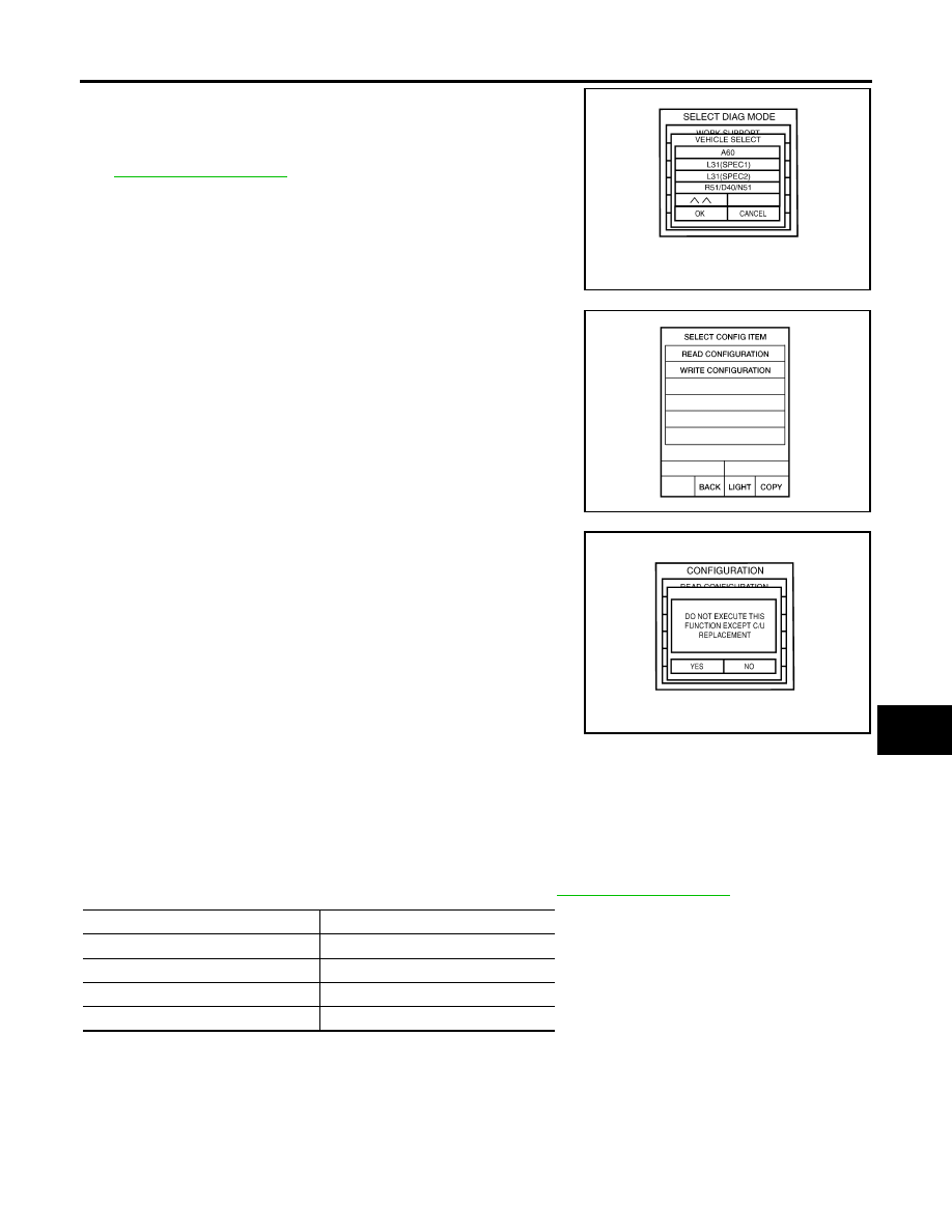
6.
Touch “R51/D40/N51” and "OK" on “VEHICLE SELECT” screen.
For canceling, touch "CANCEL" on "VEHICLE SELECT" screen.
NOTE:
Confirm vehicle model on IDENTIFICATION PLATE. Refer to
7.
Touch “WRITE CONFIGURATION” on “SELECT CONFIG
ITEM” screen.
8.
Touch "YES”.
For canceling, touch "NO".
9.
Using the following flow chart, identify the correct model and configuration list. Confirm and/or change set-
ting value for each item according to the configuration list.
Depending on CONSULT-II software version being used, some or all of the write configuration items
shown in the following configuration lists may be displayed. If an item does not appear on the CONSULT-
II "WRITE CONFIGURATION" screen(s), then it is an auto setting item and it cannot be manually set or
changed.
NOTE:
Confirm vehicle model on IDENTIFICATION PLATE. Refer to
10. Touch "CHNG SETTING" on "WRITE CONFIGURATION" screen.
CAUTION:
Make sure to touch "CHNG SETTING" even if the indicated configuration of new BCM is same as
the desirable configuration.
If not, configuration which is set automatically by selecting vehicle model cannot be memorized.
LKIA0613E
LKIA0547E
LKIA0175E
ITEM
SET VAL
AUTO LIGHT
WITH
⇔
WITHOUT
DTRL
WITH
⇔
WITHOUT
SPEED SNS WIP
WITH
⇔
WITHOUT
THEFT ALARM
WITH
⇔
WITHOUT