Nissan Pathfinder (2007 year). Manual - part 64


  Index      Manuals     Nissan Pathfinder (2007 year) - Service and Repair Manual


Search            copyright infringement  


Content      ..     62      63      64      65     ..


Nissan Pathfinder (2007 year). Manual - part 64


REFRIGERANT LINES

ATC-163

C

D

E

F

G

H

I

K

L

M

A

B

ATC

2007 Pathfinder

Removal and Installation for Compressor Clutch
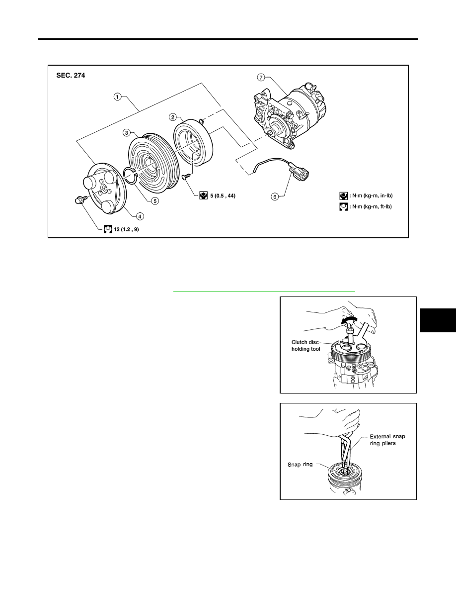
EJS004Q9

Magnet Clutch Assembly

REMOVAL

1.

Remove the compressor. Refer to 

ATC-162, "Removal and Installation for Compressor"

 .

2.

Remove the center bolt while holding the clutch disc stationary
using Tool as shown.

3.

Remove the clutch disc.

4.

Remove the snap ring using external snap ring pliers or suitable
tool.

WJIA1162E

1.

Magnet clutch assembly

2.

Magnet coil

3.

Pulley

4.

Clutch disc

5.

Snap ring

6.

Thermal protector (built in)

7.

Compressor

Tool number

: J-44614

WHA228

RHA072C

ATC-164

REFRIGERANT LINES

2007 Pathfinder

5.

Remove the pulley using Tool with a small adapter. Position the
small adapter on the end of the drive shaft and the center of the
puller on the small adapter.

CAUTION:

To prevent deformation of the pulley groove, the puller
claws should be hooked under the pulley groove and not
into the pulley groove.

6.

Remove the magnet coil harness clip using a screwdriver,
remove the three magnet coil fixing screws and remove the
magnet coil.

INSPECTION
Clutch Disc

If the contact surface shows signs of damage due to excessive heat,
replace clutch disc and pulley.

Pulley

Check the appearance of the pulley assembly. If contact surface of pulley shows signs of excessive grooving,
replace clutch disc and pulley. The contact surfaces of the pulley assembly should be cleaned with a suitable
solvent before reinstallation.

Coil

Check magnet coil for loose connections or any cracked insulation.

INSTALLATION

1.

Install the magnet coil.

CAUTION:

Be sure to align the magnet coil pin with the hole in the
compressor front head.

Tool number

: KV99233130 (J-29884)

WJIA1017E

WHA212

WHA183

WHA213

REFRIGERANT LINES

ATC-165

C

D

E

F

G

H

I

K

L

M

A

B

ATC

2007 Pathfinder

2.

Install the magnet coil harness clip using a screwdriver.

3.

Install the pulley assembly using Tool and a wrench, then install
the snap ring using snap ring pliers.

4.

Install the clutch disc on the compressor shaft, together with the
original shim(s). Press the clutch disc down by hand.

5.

Install the clutch pulley bolt using Tool, to prevent the clutch disc
from turning and tighten the bolt to specification. Refer to 

ATC-

160, "Components"

 .

CAUTION:

After tightening the clutch pulley bolt, check that the clutch
pulley rotates smoothly.

6.

Check the pulley clearance all the way around the clutch disc as
shown.

7.

If the specified clearance is not obtained, replace the adjusting
spacer to readjust.

8.

Install the compressor. Refer to 

ATC-162, "Removal and Instal-

lation for Compressor"

 .

Tool number

:

(J-38873-A)

WJIA1016E

WHA184

Tool number

: J-44614

WHA229

Clutch disc-to-pulley clearance

: 0.3 - 0.6 mm 
(0.012 - 0.024 in)

WHA194

ATC-166

REFRIGERANT LINES

2007 Pathfinder

BREAK-IN OPERATION

When replacing compressor clutch assembly, always conduct the break-in operation. This is done by engag-
ing and disengaging the clutch about 30 times. Break-in operation raises the level of transmitted torque.

Removal and Installation for Front High-pressure Flexible A/C Hose

EJS004QA

REMOVAL

1.

Remove the front left wheel and tire assembly. Refer to 

WT-7, "Rotation"

 .

2.

Remove the front left mud guard.

3.

Remove the front left splash shield.

4.

Discharge the refrigerant. Refer to 

ATC-158, "HFC-134a (R-134a) Service Procedure"

 .

5.

Remove the front high-pressure flexible A/C hose. Refer to 

ATC-160, "Components"

 .

CAUTION:

Cap or wrap the joint of the pipe with suitable material such as vinyl tape to avoid the entry of air. 

INSTALLATION

Installation is in the reverse order of removal.
Refer to 

ATC-160, "Components"

 .

CAUTION:

Replace the O-ring of the front high-pressure flexible A/C hose with a new one, then apply com-
pressor oil to it for installation.

After charging refrigerant, check for leaks.

Removal and Installation for Front High-pressure A/C Pipe

EJS004QB

REMOVAL

1.

Remove the front right wheel and tire assembly. Refer to 

WT-7, "Rotation"

 .

2.

Remove the front right mud guard.

3.

Remove the front right splash shield.

4.

Discharge the refrigerant. Refer to 

ATC-158, "HFC-134a (R-134a) Service Procedure"

 .

5.

Remove the front low pressure A/C pipe. Refer to 

ATC-167, "Removal and Installation for Front Low-pres-

sure A/C Pipe"

 .

6.

Remove the front high-pressure A/C pipe. Refer to 

ATC-160, "Components"

 .

CAUTION:

Cap or wrap the joint of the pipe with suitable material such as vinyl tape to avoid the entry of air. 

INSTALLATION

Installation is in the reverse order of removal.
Refer to 

ATC-160, "Components"

 .

CAUTION:

Replace the O-ring of the front high-pressure A/C pipe with a new one, then apply compressor oil
to it for installation.

After charging refrigerant, check for leaks.

Removal and Installation for Front Low-pressure Flexible A/C Hose

EJS004QC

REMOVAL

1.

Remove the front right wheel and tire assembly. Refer to 

WT-7, "Rotation"

 .

2.

Remove the front right mud guard.

3.

Remove the front right splash shield.

4.

Discharge the refrigerant. Refer to 

ATC-158, "HFC-134a (R-134a) Service Procedure"

 .

CAUTION:

Cap or wrap the joint of the pipe with suitable material such as vinyl tape to avoid the entry of air. 

5.

Remove the front low-pressure flexible A/C hose. Refer to 

ATC-160, "Components"

 .

INSTALLATION

Installation is in the reverse order of removal.
Refer to 

ATC-160, "Components"

 .

REFRIGERANT LINES

ATC-167

C

D

E

F

G

H

I

K

L

M

A

B

ATC

2007 Pathfinder

CAUTION:

Replace the O-ring of the front low-pressure flexible A/C hose with a new one, then apply com-
pressor oil to it for installation.

After charging refrigerant, check for leaks.

Removal and Installation for Front Low-pressure A/C Pipe

EJS004QD

REMOVAL

1.

Discharge the refrigerant. Refer to 

ATC-158, "HFC-134a (R-134a) Service Procedure"

 .

2.

Disconnect the heater pump connector.

3.

Remove the heater pump from the bracket and reposition out of the way. Do not disconnect the heater
hoses from the heater pump.

4.

Remove the front low-pressure A/C pipe. Refer to 

ATC-160, "Components"

 .

CAUTION:

Cap or wrap the joint of the pipe with suitable material such as vinyl tape to avoid the entry of air. 

INSTALLATION

Installation is in the reverse order of removal.
Refer to 

ATC-160, "Components"

 .

CAUTION:

Replace the O-ring of the front low-pressure A/C pipe with a new one, then apply compressor oil to
it for installation.

After charging refrigerant, check for leaks.

Removal and Installation for Rear High- and Low-pressure A/C Pipes

EJS004QE

REMOVAL

1.

Discharge the refrigerant. Refer to 

ATC-158, "HFC-134a (R-134a) Service Procedure"

 .

2.

Remove the luggage side lower finisher RH. Refer to 

EI-28, "Components"

 .

3.

Remove the rear high- and low-pressure A/C pipes. Refer to 

ATC-160, "Components"

 .

CAUTION:

Cap or wrap the joint of the pipe with suitable material such as vinyl tape to avoid the entry of air. 

INSTALLATION

Installation is in the reverse order of removal.
Refer to 

ATC-160, "Components"

 .

CAUTION:

Replace the O-ring of the rear high- and low-pressure A/C pipes with a new one, then apply com-
pressor oil to it for installation.

After charging refrigerant, check for leaks.

Removal and Installation for Underfloor Rear High- and Low-pressure A/C and 
Heater Core Pipes

EJS004QF

REMOVAL

1.

Release the fuel pressure. Refer to 

EC-79, "FUEL PRESSURE RELEASE"

 .

2.

Drain the engine coolant. Refer to 

CO-10, "Changing Engine Coolant"

 .

3.

Disconnect the negative battery terminal.

4.

Discharge the refrigerant. Refer to 

ATC-158, "HFC-134a (R-134a) Service Procedure"

 .

5.

Remove the rear bumper. Refer to 

EI-15, "REAR BUMPER"

 .

6.

Disconnect the fuel filler pipe and vent pipe from the lower fuel filler hose and fuel tank.

7.

Remove the front fender protector. Refer to 

EI-21, "Removal and Installation of Front Fender Protector"

 .

8.

Disconnect the chassis harness connector.

9.

Remove the front and rear RH wheels and tires. Refer to 

WT-6, "WHEEL AND TIRE ASSEMBLY"

 .

10. Disconnect the fuel feed hose quick connectors. Disconnect the quick connectors as follows:

Hold the sides of the connector, push in the tabs and pull out the tube.

If the connector and the tube are stuck together, push and pull several times until they start to move.
Then disconnect them by pulling.

ATC-168

REFRIGERANT LINES

2007 Pathfinder

CAUTION:

The quick connector can be disconnected when the tabs
are completely depressed. Do not twist the quick connec-
tor more than necessary.

Do not use any tools to disconnect the quick connector.

Keep the resin tube away from heat. Be especially careful
when welding near the tube.

Prevent any acid liquids such as battery electrolyte, from
getting on the resin tube.

Do not bend or twist the resin tube during connection. 

Do not remove the remaining retainer on the hard tube (or
the equivalent) except when the resin tube or the retainer
is replaced.

When the resin tube or hard tube, or the equivalent, is 
replaced, also replace the retainer with a new one (semi-
transparent colored retainer).

To keep the quick connector clean and to avoid damage
and contamination from foreign materials, cover the
quick connector with plastic bags or suitable material as
shown.      

11. Disconnect the frame mounted brake tubes from the brake system. Refer to 

BR-13, "BRAKE PIPING AND

HOSE"

 .

12. Remove the upper radiator mounting plates. Refer to 

CO-14, "RADIATOR"

 .

13. Disconnect the A/C lines ground strap.

14. Disconnect the exhaust system ground strap. Refer to 

EX-3, "EXHAUST SYSTEM"

 .

15. Disconnect each end of the underfloor rear high- and low-pressure A/C and heater core pipes. Refer to

ATC-160, "Components"

 .

CAUTION:

Cap or wrap the joint of the pipes with suitable material such as vinyl tape to avoid the entry of air. 

16. Remove the front floor heat shield.

17. Remove the heater pipe heat shield.

18. Disconnect the steering column from the power steering gear. Refer to 

PS-15, "POWER STEERING

GEAR AND LINKAGE"

 .

19. Set four suitable jacks at the body mount points to support the vehicle body when it is separated from the

frame.

20. Remove the body mount bolts. Refer to 

BL-117, "BODY REPAIR"

 .

21. Use the vehicle hoist to lower the frame from the body [approximately 457 mm (18 in)] until there is suffi-

cient clearance for the underfloor rear high- and low-pressure A/C and heater core pipes from the body.

22. Remove the underfloor rear high- and low-pressure A/C and heater core pipes.

PBIC1268E

PBIC0163E

REFRIGERANT LINES

ATC-169

C

D

E

F

G

H

I

K

L

M

A

B

ATC

2007 Pathfinder

INSTALLATION

Installation is in the reverse order of removal.

CAUTION:

Replace the O-ring of the underfloor rear high- and low-pressure A/C and heater core pipes with a
new one, then apply compressor oil to it for installation.

After charging refrigerant, check for leaks.

Bleed the brake system. Refer to 

BR-12, "Bleeding Brake System"

 .

Removal and Installation for Refrigerant Pressure Sensor

EJS004QG

REMOVAL

1.

Discharge the refrigerant. Refer to 

ATC-158, "HFC-134a (R-134a) Service Procedure"

 .

2.

Disconnect the refrigerant pressure sensor harness connector
and remove the refrigerant pressure sensor from the condenser.

CAUTION:

Be careful not to damage the condenser fins.

INSTALLATION

Installation is in the reverse order of removal.
Refer to 

ATC-160, "Components"

 .

CAUTION:

Be careful not to damage the condenser fins.

Replace the O-ring of the refrigerant pressure sensor with a new one, then apply compressor oil to
it for installation.

After charging refrigerant, check for leaks.

Removal and Installation for Condenser

EJS004QH

REMOVAL

1.

Discharge the refrigerant. Refer to 

ATC-158, "HFC-134a (R-134a) Service Procedure"

 .

2.

Remove the radiator. Refer to 

CO-14, "RADIATOR"

 .

CAUTION:

Be careful not to damage the core surface of the condenser and the radiator.

3.

Disconnect the front high-pressure flexible A/C hose and the front high-pressure A/C pipe from the con-
denser.

CAUTION:

Cap or wrap the joint of the pipes with suitable material such as vinyl tape to avoid the entry of air.

4.

Disconnect the refrigerant pressure sensor harness connector.

5.

Remove the refrigerant pressure sensor from the condenser.

6.

Lift the condenser out of the mounting grommets and remove
the condenser.

INSTALLATION

Installation is in the reverse order of removal.
Refer to 

ATC-160, "Components"

 .

LJIA0177E

LJIA0177E

ATC-170

REFRIGERANT LINES

2007 Pathfinder

CAUTION:

Replace the O-rings of the front high-pressure A/C pipe, refrigerant pressure sensor, and front
high-pressure flexible A/C hose with new ones, then apply compressor oil to them for installation.

After charging refrigerant, check for leaks.

Replace the mounting grommets as necessary.

Removal and Installation for Front Evaporator

EJS004QI

Front Heater and Cooling Unit Assembly

LJIA0178E


Content      ..     62      63      64      65     ..