Nissan Pathfinder (2007 year). Manual - part 59
TROUBLE DIAGNOSIS
ATC-123
C
D
E
F
G
H
I
K
L
M
A
B
ATC
2007 Pathfinder
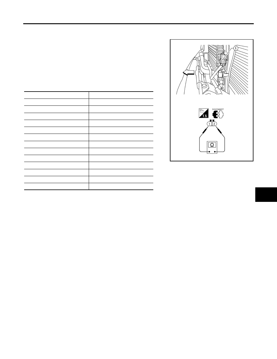
COMPONENT INSPECTION
Ambient Sensor 1
After disconnecting ambient sensor 1 (1) connector E1, measure
resistance between terminals 1 and 2 at sensor component side,
using the table below.
●
⇐
: Front
NOTE:
Both of the ambient sensors are located behind the front grille, below
the hood latch. The upper ambient sensor 1 (1) provides input for the
automatic A/C system. The lower ambient sensor 2 (2) provides
input for the compass/temperature driver information system.
If NG, replace ambient sensor 1.
Temperature
°
C (
°
F)
Resistance k
Ω
−
15 (5)
12.73
−
10 (14)
9.92
−
5 (23)
7.80
0 (32)
6.19
5 (41)
4.95
10 (50)
3.99
15 (59)
3.24
20 (68)
2.65
25 (77)
2.19
30 (86)
1.81
35 (95)
1.51
40 (104)
1.27
45 (113)
1.07
WJIA1981E