Nissan Pathfinder (2007 year). Manual - part 17


  Index      Manuals     Nissan Pathfinder (2007 year) - Service and Repair Manual


Search            copyright infringement  


Content      ..     15      16      17      18     ..


Nissan Pathfinder (2007 year). Manual - part 17


DTC P0705 PARK/NEUTRAL POSITION SWITCH

AT-107

D

E

F

G

H

I

J

K

L

M

A

B

AT

2007 Pathfinder

Diagnostic Procedure

ECS00EG6

1. 

CHECK PNP SW CIRCUIT

 With CONSULT-II

1.

Turn ignition switch ON. (Do not start engine.)

2.

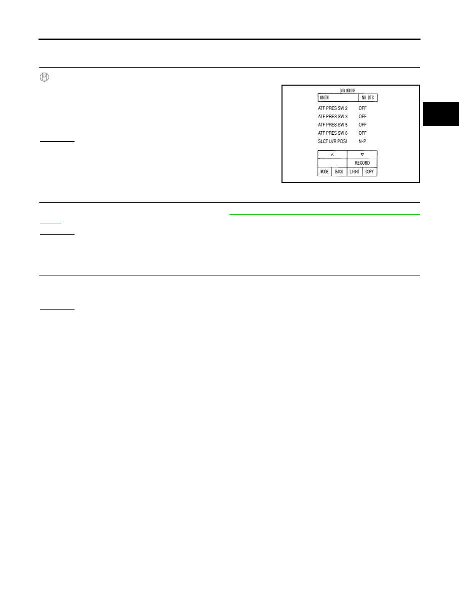
Select “SELECTION FROM MENU” in “DATA MONITOR” mode
for “A/T” with CONSULT-II.

3.

Check if correct selector lever position (N/P, R, D, 3, 2 or 1) is
displayed as selector lever is moved into each position.

OK or NG

OK

>> GO TO 5.

NG

>> GO TO 2.

2. 

CHECK TCM POWER SUPPLY AND GROUND CIRCUIT

Check TCM power supply and ground circuit. Refer to 

AT-167, "MAIN POWER SUPPLY AND GROUND CIR-

CUIT"

 .

OK or NG

OK

>> GO TO 3.

NG

>> Repair or replace damaged parts.

3. 

DETECT MALFUNCTIONING ITEM

Check the following.

A/T assembly harness connector pin terminals for damage or loose connection with harness connector.

OK or NG

OK

>> GO TO 4.

NG

>> Repair or replace damaged parts.

PCIA0034E

AT-108

DTC P0705 PARK/NEUTRAL POSITION SWITCH

2007 Pathfinder

4. 

CHECK SUB-HARNESS

1.

Remove control valve with TCM. Refer to 

AT-227, "Control Valve With TCM and A/T Fluid Temperature

Sensor 2"

 .

2.

Disconnect park/neutral position switch connector and TCM connector.

3.

Check continuity between park/neutral position switch connector
terminals and TCM connector terminals.

4.

If OK, check harness for short to ground and short to power.

5.

Reinstall any part removed.

OK or NG

OK

>> Replace the control valve with TCM. Refer to 

AT-227, "Control Valve With TCM and A/T Fluid

Temperature Sensor 2"

 .

NG

>> Replace open circuit or short to ground and short to power in harness or connectors.

5. 

CHECK DTC

Perform “DTC Confirmation Procedure”.

Refer to 

AT-105, "DTC Confirmation Procedure"

 .

OK or NG

OK

>> INSPECTION END

NG

>> GO TO 2.

Item

 Connector

Terminal

Continuity

Park/neutral position switch 
connector

F505

1

Yes

TCM connector 

F503

13

Park/neutral position switch 
connector

F505

2

Yes

TCM connector 

F503

11

Park/neutral position switch 
connector

F505

3

Yes

TCM connector 

F503

12

Park/neutral position switch 
connector

F505

5

Yes

TCM connector 

F503

14

SCIA5457E

DTC P0717 TURBINE REVOLUTION SENSOR

AT-109

D

E

F

G

H

I

J

K

L

M

A

B

AT

2007 Pathfinder

DTC P0717 TURBINE REVOLUTION SENSOR

PFP:31935

Description

ECS00EHQ

The turbine revolution sensor detects input shaft rpm (revolutions per minute). It is located on the input side of
the automatic transmission. Monitors revolution of sensor 1 and sensor 2 for non-standard conditions.

CONSULT-II Reference Value

ECS00EHR

On Board Diagnosis Logic

ECS00EHS

This is an OBD-II self-diagnostic item. 

Diagnostic trouble code “P0717 TURBINE REV S/CIRC” with CONSULT-II or 11th judgement flicker with-
out CONSULT-II is detected under the following conditions.

When TCM does not receive the proper voltage signal from the sensor.

When TCM detects an irregularity only at position of 4th gear for turbine revolution sensor 2.

Possible Cause

ECS00EHT

Harness or connectors
(The sensor circuit is open or shorted.)

Turbine revolution sensor 1, 2

DTC Confirmation Procedure

ECS00EHU

CAUTION:

Always drive vehicle at a safe speed.

Be careful not to rev engine into the red zone on the tachometer.

NOTE:
If “DTC Confirmation Procedure” has been previously performed, always turn ignition switch “OFF”
and wait at least 10 seconds before performing the next test.
After the repair, perform the following procedure to confirm the malfunction is eliminated.

 WITH CONSULT-II

1.

Turn ignition switch “ON”. (Do not start engine.)

2.

Select “DATA MONITOR” mode for “A/T” with CONSULT-II.

3.

Start engine and maintain the following conditions for at least 5
consecutive seconds.
VHCL SPEED SE: 40 km/h (25 MPH) or more
ENGINE SPEED: 1,500 rpm or more
ACCELE POS: 0.5/8 or more
Selector lever: “D” position
Gear position (Turbine revolution sensor 1): 4th or 5th posi-
tion
Gear position (Turbine revolution sensor 2): All position
Driving location: Driving the vehicle uphill (increased
engine load) will help maintain the driving conditions required for this test.

4.

If DTC is detected, go to 

AT-110, "Diagnostic Procedure"

 .

 WITH GST

Follow the procedure “WITH CONSULT-II”.

Item name

Condition 

Display value (rpm)

TURBINE REV

During driving (lock-up ON)

Approximately matches the engine speed.

BCIA0031E

AT-110

DTC P0717 TURBINE REVOLUTION SENSOR

2007 Pathfinder

Diagnostic Procedure

ECS00EHV

1. 

CHECK INPUT SIGNAL

 With CONSULT-II

1.

Start engine.

2.

Select “ECU INPUT SIGNALS” in “DATA MONITOR” mode for
“A/T” with CONSULT-II.

3.

Vehicle start and read out the value of “TURBINE REV”.

OK or NG

OK

>> GO TO 4.

NG

>> GO TO 2.

2. 

CHECK TCM POWER SUPPLY AND GROUND CIRCUIT

Check TCM power supply and ground circuit. Refer to 

AT-167, "MAIN POWER SUPPLY AND GROUND CIR-

CUIT"

 .

OK or NG

OK

>> GO TO 3.

NG

>> Repair or replace damaged parts.

3. 

DETECT MALFUNCTIONING ITEM

Check the following.

The A/T assembly harness connector pin terminals for damage or loose connection with harness connec-
tor.

OK or NG

OK

>> Replace the control valve with TCM. Refer to 

AT-227, "Control Valve With TCM and A/T Fluid

Temperature Sensor 2"

 .

NG

>> Repair or replace damaged parts.

4. 

CHECK DTC

Perform “DTC Confirmation Procedure”.

Refer to 

AT-109, "DTC Confirmation Procedure"

 .

OK or NG

OK

>> INSPECTION END

NG

>> GO TO 2.

PCIA0041E

DTC P0720 VEHICLE SPEED SENSOR A/T (REVOLUTION SENSOR)

AT-111

D

E

F

G

H

I

J

K

L

M

A

B

AT

2007 Pathfinder

DTC P0720 VEHICLE SPEED SENSOR A/T (REVOLUTION SENSOR)

PFP:32702

Description

ECS00EG7

The revolution sensor detects the revolution of the parking gear and emits a pulse signal. The pulse signal is
sent to the TCM which converts it into vehicle speed.

CONSULT-II Reference Value

ECS00EG8

On Board Diagnosis Logic

ECS00EG9

This is an OBD-II self-diagnostic item.

Diagnostic trouble code “P0720 VEH SPD SEN/CIR AT” with CONSULT-II or 1st judgement flicker without
CONSULT-II is detected under the following conditions.

When TCM does not receive the proper voltage signal from the sensor.

After ignition switch is turned “ON”, irregular signal input from vehicle speed sensor MTR before the vehi-
cle starts moving.

Possible Cause

ECS00EGA

Harness or connectors
(The sensor circuit is open or shorted.)

Revolution sensor

Vehicle speed sensor MTR

DTC Confirmation Procedure

ECS00EGB

CAUTION:

Always drive vehicle at a safe speed.

Be careful not to rev engine into the red zone on the tachometer.

NOTE:
If “DTC Confirmation Procedure” has been previously performed, always turn ignition switch “OFF”
and wait at least 10 seconds before performing the next test.
After the repair, perform the following procedure to confirm the malfunction is eliminated.

 WITH CONSULT-II

1.

Turn ignition switch “ON”. (Do not start engine.)

2.

Select “DATA MONITOR” mode for “A/T” with CONSULT-II.

3.

Drive vehicle and check for an increase of “VHCL/S SE·A/T”
value in response to “VHCL/S SE·MTR” value.
If the check result is NG, go to 

AT-114, "Diagnostic Procedure"

 .

If the check result is OK, go to following step.

4.

Select “DATA MONITOR” mode for “ENGINE” with CONSULT-II.

5.

Start engine and maintain the following conditions for at least 5
consecutive seconds.
VHCL SPEED SE: 30 km/h (19 MPH) or more
THRTL POS SEN: More than 1.0/8
Selector lever: “D” position 
Driving location: Driving the vehicle uphill (increased engine load) will help maintain the driving
conditions required for this test.
If the check result is NG, go to 

AT-114, "Diagnostic Procedure"

 .

If the check result is OK, go to following step.

6.

Maintain the following conditions for at least 5 consecutive seconds.
ENGINE SPEED: 3,500 rpm or more
THRTL POS SEN: More than 1.0/8
Selector lever: “D” position
Driving location: Driving the vehicle uphill (increased engine load) will help maintain the driving
conditions required for this test.
If the check result is NG, go to 

AT-114, "Diagnostic Procedure"

 .

Item name

Condition 

Display value (km/h)

VHCL/S SE·A/T

During driving

 Approximately matches the speedometer reading.

BCIA0031E

AT-112

DTC P0720 VEHICLE SPEED SENSOR A/T (REVOLUTION SENSOR)

2007 Pathfinder

 WITH GST

Follow the procedure “WITH CONSULT-II”.

DTC P0720 VEHICLE SPEED SENSOR A/T (REVOLUTION SENSOR)

AT-113

D

E

F

G

H

I

J

K

L

M

A

B

AT

2007 Pathfinder

Wiring Diagram — AT — VSSA/T

ECS00EGC

BCWA0322E

AT-114

DTC P0720 VEHICLE SPEED SENSOR A/T (REVOLUTION SENSOR)

2007 Pathfinder

Diagnostic Procedure

ECS00EGD

1. 

CHECK INPUT SIGNAL

 With CONSULT-II

1.

Turn ignition switch ON.

2.

Select “ECU INPUT SIGNALS” in “DATA MONITOR” mode for
“A/T” with CONSULT-II.

3.

Start the engine.

4.

Read out the value of “VHCL/S SE·A/T” while driving.
Check the value changes according to driving speed.

OK or NG

OK

>> GO TO 6.

NG

>> GO TO 2.

2. 

CHECK TCM POWER SUPPLY AND GROUND CIRCUIT

Check TCM power supply and ground circuit. Refer to 

AT-167, "MAIN POWER SUPPLY AND GROUND CIR-

CUIT"

 .

OK or NG

OK

>> GO TO 3.

NG

>> Repair or replace damaged parts.

3. 

DETECT MALFUNCTIONING ITEM

Check the following.

The A/T assembly harness connector pin terminals for damage or loose connection with harness connec-
tor.

OK or NG

OK

>> GO TO 4.

NG

>> Repair or replace damaged parts.

4. 

CHECK SUB-HARNESS

1.

Remove control valve with TCM. Refer to 

AT-227, "Control Valve With TCM and A/T Fluid Temperature

Sensor 2"

 .

2.

Disconnect park/neutral position switch connector and TCM connector.

3.

Check continuity between park/neutral position switch connector
terminals and TCM connector terminals.

4.

If OK, check harness for short to ground and short to power.

5.

Reinstall any part removed.

OK or NG

OK

>> GO TO 5.

NG

>> Replace open circuit or short to ground and short to power in harness or connectors.

SCIA2148E

Item

 Connector

Terminal

Continuity

Park/neutral position switch 
connector

F505

8

Yes

TCM connector 

F503

20

Park/neutral position switch 
connector

F505

9

Yes

TCM connector 

F503

17

Park/neutral position switch 
connector

F505

10

Yes

TCM connector 

F503

16

SCIA5458E


Content      ..     15      16      17      18     ..