Nissan Pathfinder (2007 year). Manual - part 15
TROUBLE DIAGNOSIS
AT-91
D
E
F
G
H
I
J
K
L
M
A
B
AT
2007 Pathfinder
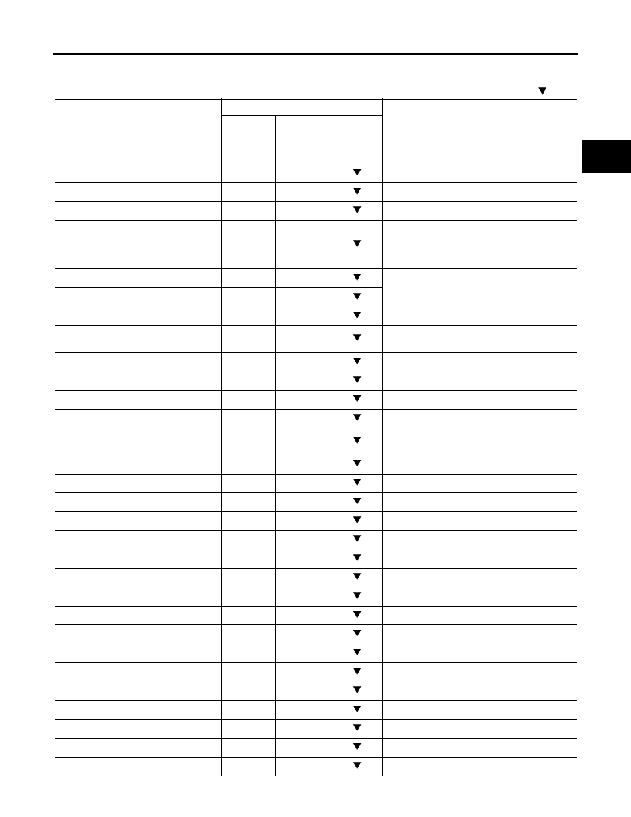
DATA MONITOR MODE
Display Items List
X: Standard, —: Not applicable,
: Option
Monitored item (Unit)
Monitor Item Selection
Remarks
ECU
INPUT
SIGNALS
MAIN SIG-
NALS
SELEC-
TION
FROM
MENU
VHCL/S SE·A/T (km/h)
X
X
Revolution sensor
VHCL/S SE·MTR (km/h)
X
—
ACCELE POSI (0.0/8)
X
—
Accelerator pedal position signal
THROTTLE POSI (0.0/8)
X
X
Degree of opening for accelerator recognized by
the TCM
For fail-safe operation, the specific value used
for control is displayed.
CLSD THL POS (ON-OFF display)
X
—
Signal input with CAN communications
W/O THL POS (ON-OFF display)
X
—
BRAKE SW (ON-OFF display)
X
—
Stop lamp switch
GEAR
—
X
Gear position recognized by the TCM updated
after gear-shifting
ENGINE SPEED (rpm)
X
X
TURBINE REV (rpm)
X
X
OUTPUT REV (rpm)
X
X
GEAR RATIO
—
X
TC SLIP SPEED (rpm)
—
X
Difference between engine speed and torque
converter input shaft speed
F SUN GR REV (rpm)
—
—
F CARR GR REV (rpm)
—
—
ATF TEMP SE 1 (V)
X
—
ATF TEMP SE 2 (V)
X
—
ATF TEMP 1 (
°
C)
—
X
ATF TEMP 2 (
°
C)
—
X
BATTERY VOLT (V)
X
—
ATF PRES SW 1 (ON-OFF display)
X
X
(for FR/B solenoid)
ATF PRES SW 2 (ON-OFF display)
X
X
(for LC/B solenoid)
ATF PRES SW 3 (ON-OFF display)
X
X
(for I/C solenoid)
ATF PRES SW 5 (ON-OFF display)
X
X
(for D/C solenoid)
ATF PRES SW 6 (ON-OFF display)
X
X
(for HLR/C solenoid)
PNP SW 1 (ON-OFF display)
X
—
PNP SW 2 (ON-OFF display)
X
—
PNP SW 3 (ON-OFF display)
X
—
PNP SW 4 (ON-OFF display)
X
—
1 POSITION SW (ON-OFF display)
X
—
1st position switch