Nissan Pathfinder (2007 year). Manual - part 14
TROUBLE DIAGNOSIS
AT-83
D
E
F
G
H
I
J
K
L
M
A
B
AT
2007 Pathfinder
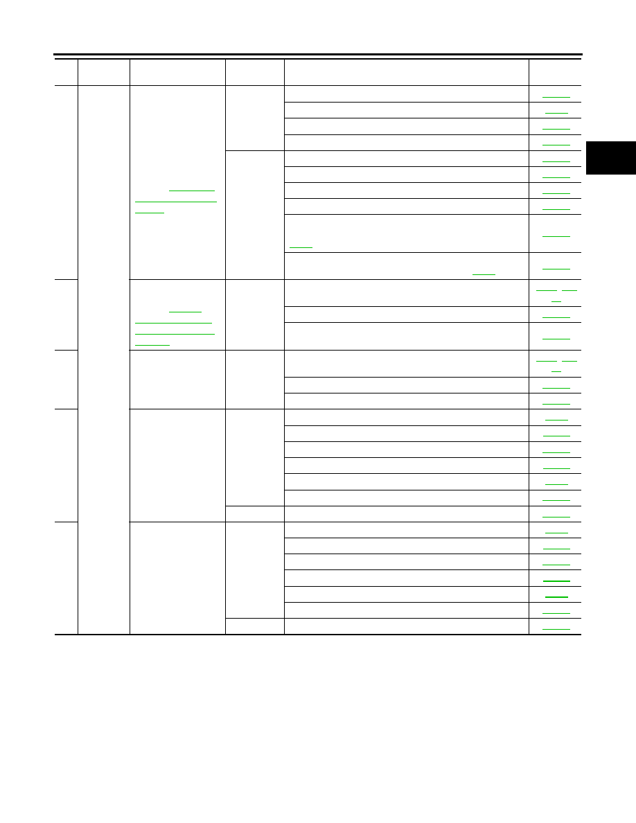
60
Others
Vehicle runs with
transmission in “N”
position.
Refer to
.
ON vehicle
1. PNP switch
2. Fluid level and state
3. Control cable adjustment
4. Control valve with TCM
OFF vehicle
5. Input clutch
6. Gear system
7. Direct clutch
8. Reverse brake
9. Forward one- way clutch (Parts behind drum support is
impossible to perform inspection by disassembly. Refer to
10. Forward brake (Parts behind drum support is impossible
to perform inspection by disassembly. Refer to
61
Engine does not start
in “N” or “P” position.
Refer to
"Engine Cannot Be
Started In “P” or “N”
Position"
.
ON vehicle
1. Ignition switch and starter
2. Control cable adjustment
3. PNP switch
62
Engine starts in posi-
tions other than “N” or
“P”.
ON vehicle
1. Ignition switch and starter
2. Control cable adjustment
3. PNP switch
63
Engine stall.
ON vehicle
1. Fluid level and state
2. Engine speed signal
3. Turbine revolution sensor
4. Torque converter clutch solenoid valve
5. CAN communication line
6. Control valve with TCM
OFF vehicle
7. Torque converter
64
Engine stalls when
select lever shifted “N”
→
“D”, “R”.
ON vehicle
1. Fluid level and state
2. Engine speed signal
3. Turbine revolution sensor
4. Torque converter clutch solenoid valve
5. CAN communication line
6. Control valve with TCM
OFF vehicle
7. Torque converter
No.
Items
Symptom
Condition
Diagnostic Item
Reference
page