Nissan Pathfinder (2006 year). Manual - part 383


  Index      Manuals     Nissan Pathfinder (2006 year) - Service and Repair Manual


Search            copyright infringement  


Content      ..     381      382      383      384     ..


Nissan Pathfinder (2006 year). Manual - part 383


AUTOMATIC DRIVE POSITIONER

SE-69

C

D

E

F

G

H

J

K

L

M

A

B

SE

2006 Pathfinder

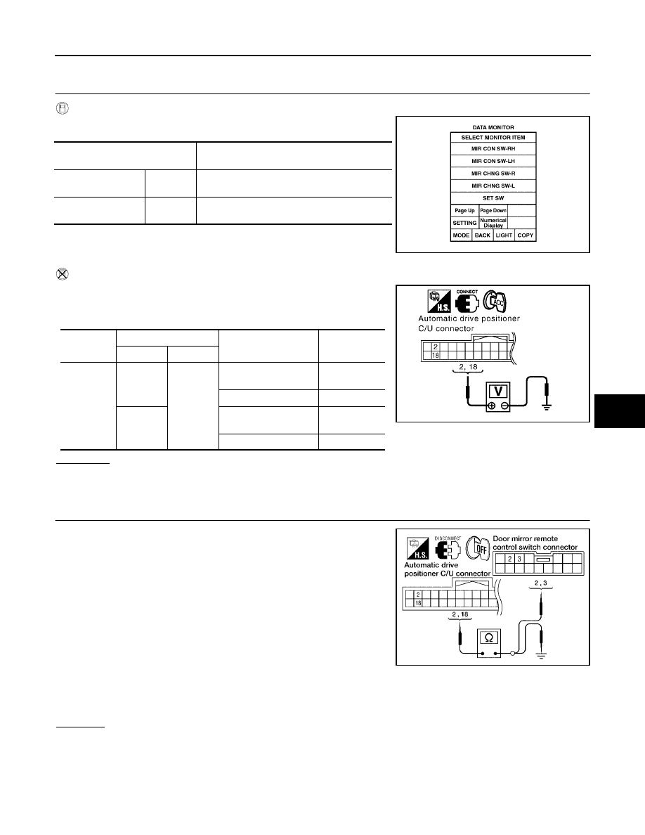
Door Mirror Remote Control Switch (Changeover Switch) Circuit Check

EIS007VP

1. 

CHECK FUNCTION 

With CONSULT-II

Check the operation on “MIR CHNG SW-R” or “MIR CHNG SW-L"
in the DATA MONITOR.

Without CONSULT-II

1.

Turn ignition switch to ACC.

2.

Check voltage between automatic drive positioner control unit
connector and ground.

OK or NG

OK

>> Door mirror remote control switch (changeover switch) is OK.

NG

>> GO TO 2.

2. 

CHECK DOOR MIRROR REMOTE CONTROL SWITCH CIRCUIT HARNESS CONTINUITY

1.

Turn ignition switch OFF.

2.

Disconnect automatic drive positioner control unit and door mir-
ror remote control switch.

3.

Check continuity between automatic drive positioner control unit
connector M33 terminals 2, 18 and door mirror remote control
switch connector M159 terminals 2, 3.

4.

Check continuity between automatic drive positioner control unit
connector M33 terminals 2, 18 and ground.

OK or NG

OK

>> GO TO 3.

NG

>> Repair or replace harness.

Monitor item [OPERATION or 

UNIT]

Contents

MIR CHNG SW-R

“ON/OFF”

ON/OFF status judged from the changeover 
switch (switching to RIGHT) signal is displayed.

MIR CHNG SW-L

“ON/OFF”

ON/OFF status judged from the changeover 
switch (switching to LEFT) signal is displayed.

PIIA0191E

Connector

Terminals

Condition

Voltage (V)

(Approx.)

(+)

(-)

M33

2

Ground

Changeover switch 
RIGHT position

0

Other than above

5

18

Changeover switch
LEFT position

0

Other than above

5

PIIA4767E

2 - 3

: Continuity should exist.

18 - 2

: Continuity should exist.

2 - Ground

: Continuity should not exist.

18 - Ground

: Continuity should not exist.

LIIA1821E

SE-70

AUTOMATIC DRIVE POSITIONER

2006 Pathfinder

3. 

CHECK DOOR MIRROR REMOTE CONTROL SWITCH (CHANGEOVER SWITCH) 

Check continuity between door mirror remote control switch as fol-
lows.

OK or NG

OK

>> Replace automatic drive positioner control unit.

NG

>> Replace door mirror remote control switch.

Door Mirror Remote Control Switch (Mirror Switch) Circuit Check

EIS007VQ

1. 

CHECK DOOR MIRROR REMOTE CONTROL SWITCH (MIRROR SWITCH) SIGNAL 

 With CONSULT-II

Check the operation on “MIR CON SW–UP/DN” and
“MIR CON SW-RH/LH” in the DATA MONITOR.

 Without CONSULT-II

1.

Turn ignition switch to ACC.

2.

Check voltage between automatic drive positioner control unit
connector and ground.

OK or NG

OK

>> Door mirror remote control switch (mirror switch) circuit is OK.

NG

>> GO TO 2.

Terminals

Condition

Continuity

3

13

Changeover switch RIGHT position

Yes

Other than above

No

2

Changeover switch LEFT position

Yes

Other than above

No

LIIA2052E

Monitor item [OPERATION or 

UNIT]

Contents

MIR CON SW-UP

“ON/

OFF”

ON/OFF status judged from the mirror switch 
(UP) signal is displayed.

MIR CON SW-DN

“ON/

OFF”

ON/OFF status judged from the mirror switch 
(DOWN) signal is displayed.

MIR CON SW-RH

“ON/

OFF”

ON/OFF status judged from the mirror switch 
(RIGHT) signal is displayed.

MIR CON SW-LH

“ON/

OFF”

ON/OFF status judged from the mirror switch 
(LEFT) signal is displayed.

PIIA0199E

Connector

Terminals

Condition

Voltage (V)

(Approx.)

(+)

(-)

M33

3

Ground

Mirror switch UP operation

0

Other than above

5

4

Mirror switch LEFT operation

0

Other than above

5

19

Mirror switch DOWN operation

0

Other than above

5

20

Mirror switch RIGHT operation

0

Other than above

5

PIIA4771E

AUTOMATIC DRIVE POSITIONER

SE-71

C

D

E

F

G

H

J

K

L

M

A

B

SE

2006 Pathfinder

2. 

CHECK HARNESS CONTINUITY

1.

Turn ignition switch OFF.

2.

Disconnect automatic drive positioner control unit and door mir-
ror remote control switch.

3.

Check continuity between automatic drive positioner control unit
connector M33 terminals 3, 4, 19, 20 and door mirror remote
control switch connector M159 terminals 4, 5, 6, 14.

4.

Check continuity between automatic drive positioner control unit connector M33 terminals 3, 4, 19, 20 and
ground.

OK or NG

OK

>> GO TO 3.

NG

>> Repair or replace harness.

3. 

CHECK DOOR MIRROR REMOTE CONTROL SWITCH (MIRROR SWITCH)

Check continuity between door mirror remote control switch as follows.

OK or NG

OK

>> Replace automatic drive positioner control unit.

NG

>> Replace door mirror remote control switch.

3 - 6

: Continuity should exist.

4 - 5

: Continuity should exist.

19 - 14

: Continuity should exist.

20 - 4

: Continuity should exist.

3 - Ground

: Continuity should not exist.

4 - Ground

: Continuity should not exist.

19 - Ground

: Continuity should not exist.

20 - Ground

: Continuity should not exist.

LIIA1823E

Terminals

Switch condition

Continuity

4

13

Mirror switch RIGHT operation

Yes

Other than above

No

5

Mirror switch LEFT operation

Yes

Other than above

No

6

Mirror switch UP operation

Yes

Other than above

No

14

Mirror switch DOWN operation

Yes

Other than above

No

LIIA2053E

SE-72

AUTOMATIC DRIVE POSITIONER

2006 Pathfinder

Door Mirror Remote Control Switch Ground Circuit Inspection

EIS007VR

1. 

CHECK DOOR MIRROR REMOTE CONTROL SWITCH GROUND CIRCUIT

1.

Turn ignition switch OFF.

2.

Disconnect door mirror remote control switch.

3.

Check continuity between door mirror remote control switch con-
nector M159 terminal 13 and ground.

OK or NG

OK

>> Check the condition of the harness and the connector.

NG

>> Repair or replace harness.

Seat Memory Switch Circuit Inspection

EIS007VS

1. 

CHECK FUNCTION

 With CONSULT-II

With “SET SW, MEMORY SW1, MEMORY SW2” on the DATA
MONITOR, operate the switch to check ON/OFF operation. 

 Without CONSULT-II

OK or NG

OK

>> Seat memory switch circuit is OK.

NG

>> GO TO 2.

13 - Ground

: Continuity should exist.

LIIA1825E

Monitor item [OPERATION or 

UNIT]

Contents

MEMORY SW1

“ON/OFF”

ON/OFF status judged from the seat memory 
switch 1 signal is displayed.

MEMORY SW2

“ON/OFF”

ON/OFF status judged from the seat memory 
switch 2 signal is displayed.

SET SW

“ON/OFF”

ON/OFF status judged from the setting 
switch signal is displayed.

Con-

nector

Terminal

Condition

Voltage (V)

(Approx.)

+

-

D5

1

4

Memory switch 1 ON

0

Memory switch 1: OFF

5

2

Memory switch 2: ON

0

Memory switch 2: OFF

5

3

Set switch: ON

0

Set switch: OFF

5

PIIA0309E

AUTOMATIC DRIVE POSITIONER

SE-73

C

D

E

F

G

H

J

K

L

M

A

B

SE

2006 Pathfinder

2. 

CHECK SEAT MEMORY SWITCH

1.

Turn ignition switch OFF.

2.

Disconnect seat memory switch.

3.

Operate the setting switch and seat memory switch.

4.

Check continuity between seat memory switch as follows.

OK or NG

OK

>> GO TO 3.

NG

>> Replace seat memory switch.

3. 

CHECK HARNESS CONTINUITY

1.

Disconnect automatic drive positioner control unit.

2.

Check continuity between automatic drive positioner control unit
connector M33 terminals 9, 24, 25 and seat memory switch con-
nector D5 terminals 1, 2, 3.

3.

Check continuity between automatic drive positioner control unit
connector M41 terminals 9, 24, 25 and ground.

OK or NG

OK

>> GO TO 4.

NG

>> Repair or replace harness.

4. 

CHECK SEAT MEMORY SWITCH GROUND CIRCUIT

Check continuity between seat memory switch D5 terminal 4 and
ground.

OK or NG

OK

>> Replace automatic drive positioner control unit.

NG

>> Repair or replace harness.

Terminal

Condition

Continuity

1

4

Memory switch 1 ON

Yes

Memory switch 1: OFF

No

2

Memory switch 2: ON

Yes

Memory switch 2: OFF

No

3

Set switch: ON

Yes

Set switch: OFF

No

LIIA1020E

9 - 1

: Continuity should exist.

24 - 3

: Continuity should exist.

25 - 2

: Continuity should exist.

9 - Ground

: Continuity should not exist.

24 - Ground

: Continuity should not exist.

25- Ground

: Continuity should not exist.

PIIA4576E

4 - Ground

: Continuity should exist. 

PIIA4821E

SE-74

AUTOMATIC DRIVE POSITIONER

2006 Pathfinder

Seat Memory Indicator Lamp Circuit Inspection

EIS007VT

1. 

CHECK FUNCTION

 With CONSULT-II

With “MEMORY SW INDCTR” in ACTIVE TEST, check operation.

 Without CONSULT-II

GO TO 2.

OK or NG

OK

>> Seat memory switch indicator lamp circuit is OK.

NG

>> GO TO 2.

2. 

CHECK SEAT MEMORY SWITCH POWER SUPPLY CIRCUIT

1.

Turn ignition switch OFF.

2.

Disconnect seat memory switch.

3.

Turn ignition switch ON.

4.

Check voltage between seat memory switch connector D5 ter-
minal 5 and ground.

OK or NG

OK

>> GO TO 3.

NG

>> Repair or replace harness.

3. 

CHECK SEAT MEMORY INDICATOR CIRCUIT HARNESS CONTINUITY

1.

Turn ignition switch OFF.

2.

Disconnect automatic drive positioner control unit.

3.

Check continuity between automatic drive positioner control unit
connector M33 terminals 12, 13 and seat memory switch con-
nector D5 terminals 6, 7. 

4.

Check continuity between automatic drive positioner control unit
connector M33 terminals 12, 13 and ground.

OK or NG

OK

>> GO TO 4.

NG

>> Repair or replace harness.

Test item

Description

MEMORY SW INDCTR

The memory switch indicator is lit by receiving the 
drive signal.

PIIA0319E

5 - Ground

: Battery voltage

PIIA4595E

12 - 6

: Continuity should exist.

13 - 7

: Continuity should exist.

12 - Ground

: Continuity should not exist.

13 - Ground

: Continuity should not exist.

LIIA1022E

AUTOMATIC DRIVE POSITIONER

SE-75

C

D

E

F

G

H

J

K

L

M

A

B

SE

2006 Pathfinder

4. 

CHECK SEAT MEMORY SWITCH INDICATOR SIGNAL

1.

Connect seat memory switch.

2.

Check voltage between automatic drive positioner control unit
connector M33 terminals 12, 13 and ground. 

OK or NG

OK

>> Replace automatic drive positioner control unit.

NG

>> Replace seat memory switch.

Door Mirror Sensor Power Supply and Ground Circuit inspection

EIS007VU

1. 

CHECK DOOR MIRROR SENSOR CIRCUIT HARNESS CONTINUITY

1.

Disconnect automatic drive positioner control unit and door mir-
ror (LH and RH).

2.

Check continuity between automatic drive positioner control unit
connector M34 terminals 33, 41 and door mirror connector D4
(LH), D107 (RH) terminals 4, 9.

3.

Check continuity between automatic drive positioner control unit
connector M34 terminals 33, 41 and ground.

OK or NG

OK

>> GO TO 2.

NG

>> Repair or replace harness.

2. 

CHECK MIRROR SENSOR POWER SUPPLY

1.

Connect automatic drive positioner control unit and door mirror
LH.

2.

Turn ignition switch to ACC.

3.

Check voltage between automatic drive positioner control unit
connector M34 terminal 33 and ground.

OK or NG

OK

>> GO TO 3.

NG

>> Replace automatic drive positioner control unit.

12 - Ground

: Battery voltage

13 - Ground

: Battery voltage

LIIA2237E

33 - 4

: Continuity should exist.

41 - 9

: Continuity should exist.

33 - Ground

: Continuity should not exist.

41 - Ground

: Continuity should not exist.

LIIA1773E

33 - Ground

: Approx. 5V

LIIA1136E

SE-76

AUTOMATIC DRIVE POSITIONER

2006 Pathfinder

3. 

CHECK MIRROR SENSOR GROUND CIRCUIT

1.

Turn ignition switch OFF.

2.

Check continuity between automatic drive positioner control unit
connector M34 terminal 41 and ground.

OK or NG

OK

>> Door mirror sensor power supply and ground circuit are

OK.

NG

>> Replace automatic drive positioner control unit.

A/T Device (Park Position Switch) Circuit Inspection

EIS007VV

1. 

CHECK FUNCTION

 With CONSULT-II

Check that when the A/T selector lever is in P position, “DETENT
SW” on the DATA MONITOR becomes OFF.

 Without CONSULT-II

1.

Turn ignition switch ON.

2.

Check voltage between driver seat control unit connector and
ground.

OK or NG

OK

>> A/T device (park position switch) circuit is OK.

NG

>> GO TO 2.

41 - Ground

: Continuity should exist.

LIIA1135E

Monitor item

 [OPERATION or UNIT]

Contents

DETENT SW

“ON/

OFF”

The selector lever position “P position (OFF)/other than P 
position (ON)” judged from the park switch signal is dis-
played.

PIIA0291E

Connector

Terminals

Condition

Voltage (V) 

(Approx.)

(+)

(-)

Driver seat 

control unit: P2

21

Ground

A/T selector lever 
in P position

0

A/T selector lever 
in other than P 
position

Battery voltage

LIIA2238E


Content      ..     381      382      383      384     ..