Nissan Pathfinder (2006 year). Manual - part 365


  Index      Manuals     Nissan Pathfinder (2006 year) - Service and Repair Manual


Search            copyright infringement  


Content      ..     363      364      365      366     ..


Nissan Pathfinder (2006 year). Manual - part 365


SUNROOF

RF-21

C

D

E

F

G

H

J

K

L

M

A

B

RF

2006 Pathfinder

4. 

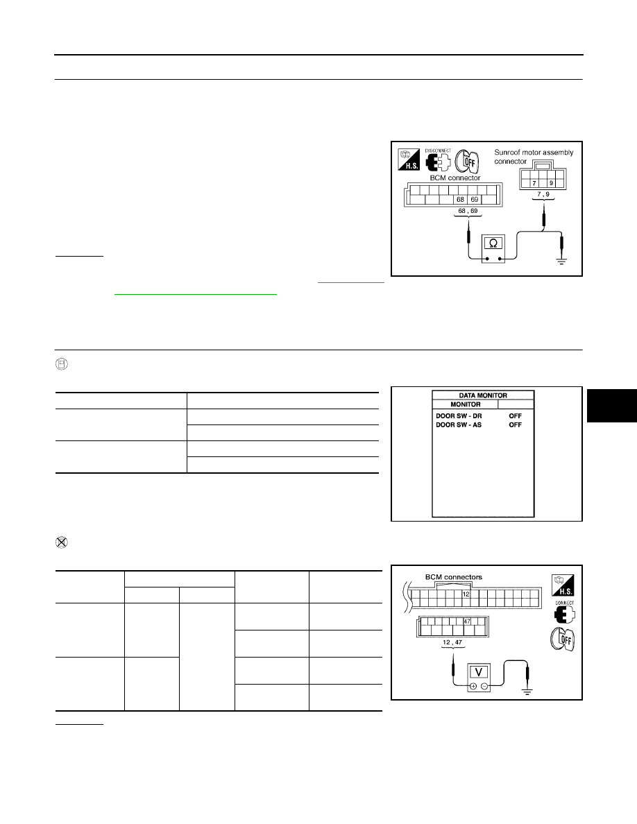
CHECK SUNROOF MOTOR CIRCUIT

1.

Turn ignition switch OFF.

2.

Disconnect BCM and sunroof motor assembly connectors.

3.

Check continuity between BCM connector M20 terminals 68, 69 and sunroof motor assembly connector
B83 terminals 7, 9.

4.

Check continuity between BCM connector M20 terminals 68, 69
and ground.

OK or NG

OK

>> Sunroof motor assembly power supply circuits are OK.

Further inspection is necessary. Refer to 

RF-18, "Trou-

ble Diagnosis Chart by Symptom"

 .

NG

>> Repair or replace harness.

Door Switch Check 

EIS007TG

1. 

CHECK DOOR SWITCH INPUT SIGNAL

 With CONSULT-II

Check ("DOOR SW-DR" and "DOOR SW-AS") in "DATA MONITOR" mode with CONSULT-II.

Without CONSULT-II

Check voltage between BCM connector M18, M19 terminals 12, 47 and ground.

OK or NG

OK

>> Door switch circuit is OK.

NG

>> GO TO 2.

68 - 9

: Continuity should exist.

69 - 7

: Continuity should exist.

68 - Ground

: Continuity should not exist.

69 - Ground

: Continuity should not exist.

LIIA1683E

Monitor item

Condition

DOOR SW-DR

DOOR OPEN

: ON

DOOR CLOSED

: OFF

DOOR SW-AS

DOOR OPEN

: ON

DOOR CLOSED

: OFF

PIIA2464E

Item

Terminal

Condition

Voltage

(Approx.)

(+)

(–)

RH door switch 

12

Ground

DOOR OPEN 

(Switch closed)

0

DOOR CLOSED 

(Switch open)

Battery voltage

LH door switch

47

DOOR OPEN 

(Switch closed)

0

DOOR CLOSED 

(Switch open)

Battery voltage

WIIA0234E

RF-22

SUNROOF

2006 Pathfinder

2. 

CHECK DOOR SWITCH CIRCUIT

1.

Turn ignition switch OFF.

2.

Disconnect door switch and BCM connectors.

3.

Check continuity between BCM connector M18, M19 terminals
12, 47 and door switch connectors B8, B108 terminal 2.

4.

Check continuity between BCM connector M18, M19 terminals
12, 47 and ground.

OK or NG

OK

>> GO TO 3.

NG

>> Repair or replace harness.

3. 

CHECK DOOR SWITCH

Check continuity between door switches terminal 2 and ground part
of door switch.

OK or NG

OK

>> GO TO 4.

NG

>> Replace malfunctioning door switch.

4. 

CHECK BCM OUTPUT SIGNAL

1.

Connect BCM connectors.

2.

Check voltage between BCM connector M18, M19 terminals 12,
47 and ground.

OK or NG

OK

>> Further inspection is necessary. Refer to 

RF-18, "Trou-

ble Diagnosis Chart by Symptom"

 .

NG

>> Replace BCM. Refer to 

BCS-27, "Removal and Installa-

tion"

 .

Front door LH

47 - 2

: Continuity should exist.

Front door RH

12 - 2

: Continuity should exist.

12 - Ground

: Continuity should not exist.

47 - Ground

: Continuity should not exist.

WIIA0626E

Terminal

Door switch

Continuity

2

Ground part of 

door switch

Pushed

No

Released

Yes

WIIA0289E

12 - Ground

: Battery voltage

47 - Ground

: Battery voltage

WIIA0234E

SUNROOF

RF-23

C

D

E

F

G

H

J

K

L

M

A

B

RF

2006 Pathfinder

Adjustment

EIS007TH

Inspect then measure the gap and height difference between the glass lid assembly and roof panel; compare
to specifications. Determine which procedure to follow based on results of measurements. 

GAP ADJUSTMENT 

If a gap or minor height difference between glass lid assembly and roof panel is found, adjust in the following
manner:

1.

Open sunshade assembly and tilt glass lid assembly up.

2.

Loosen glass lid assembly screws (2 each on left and right sides), then tilt glass lid assembly down.

3.

Manually adjust glass lid assembly from outside of vehicle so it is within specification "A-A" as shown.

4.

After adjustment, tilt glass lid assembly up and tighten screws.

5.

Tilt glass lid assembly up and down several times to check that it moves and seals properly.

HEIGHT DIFFERENCE ADJUSTMENT

If an excessive height difference between glass lid assembly and roof panel is found, adjust in the following
manner:

1.

Remove headlining. Refer to 

EI-30, "HEADLINING"

 .

2.

Loosen sunroof frame assembly nuts and sunroof bracket bolts.

3.

Add shims until gap is within specification "A-A" as shown.

NOTE:
Temporarily snug nuts and bolts to prevent movement between each adjustment.

4.

Tilt glass lid assembly up and down several times to check that it moves and seals properly.

5.

Tighten sunroof frame assembly nuts and sunroof bracket bolts. 

NOTE:
First tighten left front then right rear sunroof frame assembly nuts to prevent uneven torque while tighten-
ing remaining sunroof bracket bolts.

6.

Install headlining. Refer to 

EI-30, "HEADLINING"

 .

A.

0.8 

±

 1.5mm (0.03 

±

 0.06 in.)

B.

4.0 

±

 0.7mm (0.16 

±

 0.03 in)

WIIA1071E

RF-24

SUNROOF

2006 Pathfinder

Removal and Installation

EIS007TI

WIIA0423E

SUNROOF

RF-25

C

D

E

F

G

H

J

K

L

M

A

B

RF

2006 Pathfinder

After any adjustment, check sunroof operation and glass lid alignment.

Handle glass lid with care so not to cause damage.

For easier installation, mark each point before removal.

CAUTION:

Always work with a helper.

Before removal, fully close the glass lid assembly. Then, after removal, do not move the motor
assembly.

After installing the sunroof and glass lid, check gap adjustment to ensure there is no malfunction.

SUNROOF UNIT
Removal

CAUTION:

Always work with a helper.

When taking sunroof unit out, use shop cloths to protect the seats and trim from damage.

After installing the sunroof unit and glass lid, be sure to check gap adjustment to ensure there is
no malfunction.

1.

Remove headlining. Refer to 

EI-30, "Removal and Installation"

 . 

2.

Remove the sunroof glass lid. Refer to 

RF-25, "GLASS LID"

 .

3.

Disconnect sunroof motor and remove the overhead console bracket.

4.

Disconnect the drain hoses.

5.

Remove front sunroof frame assembly nuts.

6.

Remove the rear sunroof bracket bolts. 

7.

Remove the side bolts and the sunroof unit.

Installation

1.

Position the sunroof frame assembly and install the side bolts.

2.

Install the rear sunroof bracket bolts.

3.

Install front sunroof frame assembly nuts.

4.

Connect the drain hoses.

5.

Install the overhead console bracket and connect the sunroof motor.

6.

Install the sunroof glass lid. Refer to 

RF-25, "GLASS LID"

 .

7.

Install headlining. Refer to 

EI-30, "Removal and Installation"

 .

GLASS LID
Removal

1.

Open sunshade.

2.

Ensure glass lid is closed.

3.

Remove the screws securing glass lid to the sunroof frame assembly.

4.

Remove the glass lid assembly.

Installation

1.

Position glass lid to sunroof assembly.

1.

Glass lid assembly

2.

Wind deflector

3.

Rear drain hoses

4.

Shade stoppers

5.

Sunroof bracket 

6.

Sunroof frame assembly

7.

Front drain hoses

8.

Sunroof motor assembly

9.

Sunshade assembly

RF-26

SUNROOF

2006 Pathfinder

2.

Install the glass lid assembly screws. (First tighten left front bolt,
then tighten right rear bolt on glass lid to prevent lid from moving
while tightening other bolts.) 

3.

Adjust the sunroof glass. Refer to 

RF-23, "Adjustment"

 .

WIND DEFLECTOR
Removal

1.

Open the sunroof.

2.

Remove screws from the left, center, and right side wind deflec-
tor holders.

3.

Remove the wind deflector from the sunroof frame assembly.

Installation

Installation is in the reverse order of removal.

SUNSHADE
Removal

1.

Remove the sunroof frame assembly. Refer to 

RF-25, "SUNROOF UNIT"

 .

2.

Remove the sunshade stoppers (2 points) from the rear end of
the sunroof frame assembly.

3.

Remove the sunshade assembly from the rear end of the sun-
roof frame assembly.

Installation

Installation is in the reverse order of removal.

SUNROOF MOTOR
Removal

CAUTION:

When removing the sunroof motor, be sure that the sunroof is in the fully closed position.

Never run the removed motor as a single unit.

1.

Position the sunroof assembly in the fully closed position.

2.

Remove the front roof console assembly. Refer to 

EI-30, "Removal and Installation"

 .

WIIA0252E

WIIA0424E

LIIA1672E

SUNROOF

RF-27

C

D

E

F

G

H

J

K

L

M

A

B

RF

2006 Pathfinder

3.

Disconnect the harness connector from the sunroof motor
assembly.

4.

Remove the mounting screws and the sunroof motor assembly.

Installation

CAUTION:

Before installing the sunroof motor assembly, be sure to place the link and wire assembly in the sym-
metrical and fully closed position.

1.

Move the sunroof motor assembly laterally little by little so that
the gear is completely engaged into the wire on the sunroof unit
and the mounting surface becomes parallel. Then secure the
motor with bolts.

2.

Connect the harness connector to the sunroof motor assembly.

3.

Install the front roof console assembly. Refer to 

EI-30, "Removal and Installation"

 .

4.

Reset the sunroof motor memory. Refer to 

RF-12, "RE-TEACHING PROCEDURE"

 .

DRAIN HOSES
Removal

LIIA1673E

LIIA1674E

1.

Drain hoses

WIIA1072E

RF-28

SUNROOF

2006 Pathfinder

1.

Remove the headlining. Refer to 

EI-30, "Removal and Installation"

 .

2.

Visually check the drain hoses for proper connections, damage or deterioration.

3.

Remove each drain hose and check visually for damage, cracks or deterioration.

4.

Pour water through the drain hose to check for damage.

If any damage is found, replace the drain hose.

Installation

Installation is in the reverse order of removal.

WEATHERSTRIP

Visually check weatherstrip for any damage, deterioration, or flattening. 

In the case of leakage around glass lid, close glass lid and pour water around it to find the damaged or
gaped portion, remove glass lid assembly. Refer to: 

RF-25, "Removal"

 .

If any damage is found, replace glass lid assembly. Refer to: 

RF-25, "GLASS LID"

 .

CAUTION:

Do not remove weatherstrip.

LINK AND WIRE ASSEMBLY

NOTE:
Before replacing any suspect part, be sure it is the source of the noise.

1.

Visually check to determine if a sufficient amount of petroleum jelly has been applied to the wire or rail
groove. If not, add petroleum jelly as required.

2.

Check wire for any damage or deterioration. If any damage is found, remove rear guide, then replace
wire.

LIIA0272E


Content      ..     363      364      365      366     ..