Nissan Pathfinder (2006 year). Manual - part 357
FUSE AND RELAY BOX
PG-85
C
D
E
F
G
H
I
J
L
M
A
B
PG
2006 Pathfinder
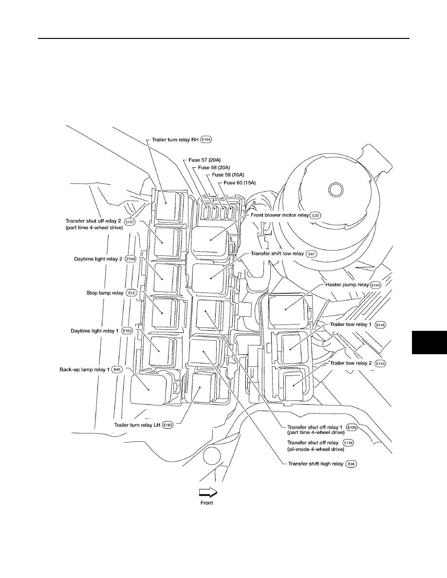
FUSE AND RELAY BOX
PFP:24012
Terminal Arrangement
EKS00G91
WKIA5014E
|
|
|
FUSE AND RELAY BOX PG-85 C D E F G H I J L M A B PG 2006 Pathfinder FUSE AND RELAY BOX PFP:24012 Terminal Arrangement EKS00G91 WKIA5014E |