Nissan Pathfinder (2006 year). Manual - part 335


  Index      Manuals     Nissan Pathfinder (2006 year) - Service and Repair Manual


Search            copyright infringement  


Content      ..     333      334      335      336     ..


Nissan Pathfinder (2006 year). Manual - part 335


TROUBLE DIAGNOSIS

MTC-33

C

D

E

F

G

H

I

K

L

M

A

B

MTC

2006 Pathfinder

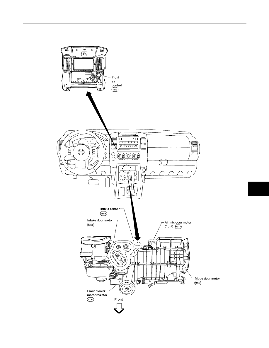
PASSENGER COMPARTMENT

WJIA1301E

MTC-34

TROUBLE DIAGNOSIS

2006 Pathfinder

Schematic

EJS004RI

WJWA0396E

TROUBLE DIAGNOSIS

MTC-35

C

D

E

F

G

H

I

K

L

M

A

B

MTC

2006 Pathfinder

Wiring Diagram — A/C,M —

EJS004RJ

WJWA0397E

MTC-36

TROUBLE DIAGNOSIS

2006 Pathfinder

WJWA0280E

TROUBLE DIAGNOSIS

MTC-37

C

D

E

F

G

H

I

K

L

M

A

B

MTC

2006 Pathfinder

WJWA0281E

MTC-38

TROUBLE DIAGNOSIS

2006 Pathfinder

WJWA0199E

TROUBLE DIAGNOSIS

MTC-39

C

D

E

F

G

H

I

K

L

M

A

B

MTC

2006 Pathfinder

Front Air Control Terminals and Reference Value

EJS004RK

Measure voltage between each terminal and ground by following
Terminals and Reference Value for front air control.

PIN CONNECTOR TERMINAL LAYOUT

TERMINALS AND REFERENCE VALUE FOR FRONT AIR CONTROL

WJIA1302E

WJIA1303E

Termi-

nal No.

Wire 

color

Item

Ignition 

switch

Condition

Voltage (V)

(Approx.)

1

BR

Mode door motor CW

ON

Clockwise rotation

Battery voltage

2

W

Air mix door motor (Driver) CW

ON

Clockwise rotation

Battery voltage

3

G/R

Air mix door motor (Driver) CCW

ON

Counterclockwise rotation

Battery voltage

4

Y

Intake door motor CW

ON

Clockwise rotation

Battery voltage

5

O

Intake door motor CCW

ON

Counterclockwise rotation

Battery voltage

6

W/G

Power supply for IGN

ON

-

Battery voltage

10

W

Compressor ON signal

ON

A/C switch OFF

5V

ON

A/C switch ON

0V

11

Y

Rear defrost request

ON

-

Battery voltage

12

L

Intake sensor

ON

-

0 - 5V

13

V

Sensor ground

ON

-

0 - 5V

14

R

Mode door motor CCW

ON

Counterclockwise rotation

Battery voltage

18

BR

Front blower monitor

ON

Front blower motor OFF

Battery voltage

Front blower motor ON

0V

19

R/Y

Power supply for BAT

-

-

Battery voltage

20

B

Ground

-

-

0V

21

V

Mode door motor feedback

ON

-

0 - 5V

22

SB

Air mix door motor (Front) feedback

ON

-

0 - 5V

23

G

Power supply for mode door motor 
and air mix door motor (Front) PBR

ON

-

 5V

25

R

Rear defroster request

ON

-

Battery voltage

26

P

Ground for mode door motor and air 
mix door motor (Front) PBR

 ON

-

0V

MTC-40

TROUBLE DIAGNOSIS

2006 Pathfinder

Operational Check

EJS004RL

The purpose of the operational check is to confirm that the system operates properly.

CHECKING BLOWER

1.

Turn blower control dial clockwise. Blower should operate on low speed. 

2.

Turn the blower control dial again, and continue checking each blower speed until all speeds are checked.

3.

Leave blower on speed 4. 

If NG, go to trouble diagnosis procedure for 

MTC-57, "Front Blower Motor Circuit"

 .

If OK, continue with next check.

CHECKING DISCHARGE AIR

1.

Turn the mode switch to each position.

2.

Confirm that discharge air comes out according to the air distribution table.

Mode door position is checked in the next step.
If NG, go to trouble diagnosis procedure for 

MTC-45, "Mode Door Motor Circuit"

 .

If OK, continue with next check.

NOTE:
Confirm that the A/C compressor clutch is engaged (sound or visual inspection) and intake door position is at
fresh when the DEF (

) or D/F (

) is selected.

DISCHARGE AIR FLOW

CHECKING RECIRCULATION

1.

Press recirculation (

) switch one time. Recirculation indicator should illuminate.

2.

Press recirculation (

) switch one more time. Recirculation indicator should go off.

3.

Listen for intake door position change (blower sound should change slightly).

If NG, go to trouble diagnosis procedure for 

MTC-53, "Intake Door Motor Circuit"

 .

If OK, continue with next check.

NOTE:
Confirm that the compressor clutch is engaged (sound or visual inspection) and intake door position is at fresh
when the DEF or D/F is selected.

CHECKING TEMPERATURE DECREASE

1.

Rotate temperature control dial counterclockwise.

2.

Check for cold air at appropriate discharge air outlets.

If NG, listen for sound of air mix door motor operation if OK, go to trouble diagnosis procedure fo

MTC-70,

"Insufficient Cooling"

 . If air mix door motor appears to be malfunctioning, go to 

MTC-51, "DIAGNOSTIC PRO-

CEDURE FOR AIR MIX DOOR MOTOR (FRONT)"

 .

If OK, continue with next check.

CHECKING TEMPERATURE INCREASE

1.

Rotate temperature control dial clockwise.

2.

Check for hot air at appropriate discharge air outlets.

Conditions

: Engine running and at normal operating temperature

Mode door position

Air outlet/distribution

Vent

Foot

Defroster

95%

5%

60%

40%

20%

55%

25%

15%

50%

35%

7%

15%

78%

Airflow always present at side demisters


Content      ..     333      334      335      336     ..