Nissan Pathfinder (2006 year). Manual - part 330


  Index      Manuals     Nissan Pathfinder (2006 year) - Service and Repair Manual


Search            copyright infringement  


Content      ..     328      329      330      331     ..


Nissan Pathfinder (2006 year). Manual - part 330


CHASSIS AND BODY MAINTENANCE

MA-27

C

D

E

F

G

H

I

J

K

M

A

B

MA

2006 Pathfinder

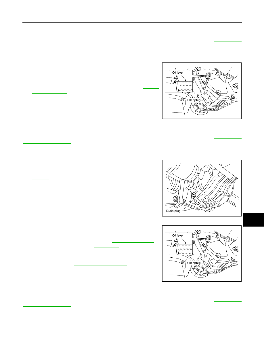
Checking Front Final Drive Oil

ELS001OV

CAUTION:

If using the vehicle for towing, the final drive oil must be replaced as specified. Refer to 

MA-7, "PERI-

ODIC MAINTENANCE"

 .

OIL LEAKAGE AND OIL LEVEL

1.

Make sure that oil is not leaking from the final drive assembly or around it.

2.

Check oil level from the filler plug hole as shown.

CAUTION:

Do not start engine while checking oil level.

3.

Install the filler plug with a new gasket on it to the final drive
assembly. Tighten to the specified torque. Refer to 

FFD-16,

"COMPONENTS"

 .

CAUTION:

Do not reuse gasket.

Changing Front Final Drive Oil

ELS001OW

CAUTION:

If using the vehicle for towing, the final drive oil must be replaced as specified. Refer to 

MA-7, "PERI-

ODIC MAINTENANCE"

 .

DRAINING

1.

Stop the engine.

2.

Remove the drain plug and gasket. Drain the gear oil.

3.

Install the drain plug with a new gasket to the final drive asssem-
bly. Tighten to the specified torque. Refer to 

FFD-16, "COMPO-

NENTS"

 .

CAUTION:

Do not reuse gasket.

FILLING

1.

Remove the filler plug and gasket. Fill with new gear oil until the
oil level reaches the specified level near the filler plug hole.

2.

After refilling oil, check the oil level. Install the filler plug with a
new gasket on it to the final drive assembly. Tighten to the spec-
ified torque. Refer to 

FFD-16, "COMPONENTS"

 .

CAUTION:

Do not reuse gasket.

Checking Rear Final Drive Oil

ELS001OX

CAUTION:

If using the vehicle for towing, the final drive oil must be replaced as specified. Refer to 

MA-7, "PERI-

ODIC MAINTENANCE"

 .

OIL LEAKAGE AND OIL LEVEL

1.

Make sure that oil is not leaking from the final drive assembly or around it.

LDIA0176E

LDIA0175E

Oil grade and capacity

Refer to 

MA-11, "Fluids and 

Lubricants"

 .

LDIA0176E

MA-28

CHASSIS AND BODY MAINTENANCE

2006 Pathfinder

2.

Check the oil level from the filler plug hole as shown.

CAUTION:

Do not start engine while checking oil level.

3.

Install the filler plug with a new gasket to the final drive assem-
bly. Tighten to the specified torque. Refer to 

RFD-16, "COMPO-

NENTS"

 .

CAUTION:

Do not reuse gasket.

Changing Rear Final Drive Oil

ELS001OY

CAUTION:

If using the vehicle for towing, the final drive oil must be replaced as specified. Refer to 

MA-7, "PERI-

ODIC MAINTENANCE"

 .

DRAINING

1.

Stop the engine.

2.

Remove the drain plug and gasket. Drain the gear oil.

3.

Install the drain plug with a new gasket to the final drive assem-
bly. Tighten to the specified torque. Refer to 

RFD-16, "COMPO-

NENTS"

 .

CAUTION:

Do not reuse gasket.

FILLING

1.

Remove the filler plug and gasket. Fill with new gear oil until the
oil level reaches the specified level near the filler plug hole.

2.

After refilling oil, check the oil level. Install the filler plug with a
new gasket to the final drive assembly. Tighten to the specified
torque. Refer to 

RFD-16, "COMPONENTS"

 .

CAUTION:

Do not reuse gasket.

Balancing Wheels

ELS001OZ

WHEEL BALANCE REMOVAL

1.

Remove wheel and tire using power tool.

2.

Using releasing agent, remove double-faced adhesive tape from the wheel.

CAUTION:

Be careful not to scratch the wheel during removal.

After removing double-faced adhesive tape, wipe clean traces of releasing agent from the
wheel.

WHEEL BALANCE INSTALLATION AND ADJUSTMENT

If a tire balance machine has adhesion balance weight mode settings and drive-in weight mode setting,
select and adjust a drive-in weight mode suitable for wheels.

1.

Set wheel on wheel balancer using the center hole as a guide. Start the tire balance machine.

2.

When inner and outer imbalance values are shown on the wheel balancer indicator, multiply outer imbal-
ance value by 1.6 to determine balance weight that should be used. Select the outer balance weight with

LDIA0163E

LDIA0162E

Oil grade and capacity

: Refer to 

MA-11, "Fluids and 

Lubricants"

 .

LDIA0163E

CHASSIS AND BODY MAINTENANCE

MA-29

C

D

E

F

G

H

I

J

K

M

A

B

MA

2006 Pathfinder

a value closest to the calculated value and install it to the designated outer position of, or at the desig-
nated angle in relation to the road wheel.

CAUTION:

Do not install the inner balance weight before installing the outer balance weight.

Before installing the balance weight, be sure to clean the mating surface of the wheel.

Indicated imbalance value 

×

 5/3 = balance weight to be installed

Calculation example:
23 g (0.81 oz) 

×

 5/3 = 38.33 g (1.35 oz) = 40 g (1.41 oz) balance

weight (closer to calculated balance weight value)
Note that balance weight value must be closer to the calculated
balance weight value.
Example:
37.4 g = 35 g (1.23 oz)
37.5 g = 40 g (1.41 oz)

a.

Install balance weight in the position shown.

b.

When installing balance weight to wheels, set it into the grooved
area on the inner wall of the wheel as shown so that the balance
weight center is aligned with the wheel balancer indication posi-
tion (angle).

CAUTION:

Always use Genuine NISSAN adhesion balance weights.

Balance weights are not reusable; always replace with
new ones.

Do not install more than three sheets of balance weights.

c.

If calculated balance weight value exceeds 50 g (1.76 oz), install
two balance weight sheets in line with each other as shown.

CAUTION:

Do not install one balance weight sheet on top of another.

3.

Start wheel balancer again.

4.

Install drive-in balance weight on inner side of road wheel in the
wheel balancer indication position (angle).

CAUTION:

Do not install more than two balance weights.

5.

Start wheel balancer. Make sure that inner and outer residual
imbalance values are 5 g (0.18 oz) each or below.

If either residual imbalance value exceeds 5 g (0.18 oz), repeat installation procedures.

SMA054D

WDIA0060E

SMA056D

MA-30

CHASSIS AND BODY MAINTENANCE

2006 Pathfinder

Wheel Balance (Maximum Allowable Imbalance)

Tire Rotation

ELS001P0

1.

Rotate the tires on each side from front to back as shown, using
power tool.

Follow the maintenance schedule for tire rotation service
intervals. Refer to 

MA-5, "GENERAL MAINTENANCE"

 .

Do not include the spare tire when rotating the tires.

CAUTION:

When installing wheels, tighten them diagonally by divid-
ing the work two to three times in order to prevent the
wheels from developing any distortion.

2.

Adjust the tire pressure to specification. Refer to 

WT-38, "Tire"

 .

3.

After the tire rotation, retighten the wheel nuts after the vehicle has been driven for 1,000 km (600 miles),
and also after a wheel and tire have been installed such as after repairing a flat tire.

Checking Brake Fluid Level and Leaks

ELS001P1

Check the brake fluid level in the reservoir tank. It should be
between the “MAX” and “MIN” lines on the reservoir tank.

Visually check around reservoir tank for fluid leaks.

If the fluid level is extremely low, check the brake system.

If the brake warning lamp comes on when the fluid is at the cor-
rect level, check the brake fluid level switch and the parking
brake switch.

Checking Brake Lines and Cables

ELS001P2

1.

Check the brake lines and hoses for cracks, deterioration, and
other damage. Replace any damaged parts.

CAUTION:

If brake fluid leaks are visible around the brake line joints,
retighten the joint, or replace damaged parts as necessary.

2.

Check for brake fluid leaks by fully depressing brake pedal while
engine is running.

Maximum allowable imbalance

Dynamic (at rim flange)

5 g (0.18 oz) (one side)

Static

10 g (0.35 oz)

Wheel nuts

: Refer to 

WT-6, "WHEEL AND TIRE 

ASSEMBLY"

 .

SMA829C

LFIA0234E

SBR389C

CHASSIS AND BODY MAINTENANCE

MA-31

C

D

E

F

G

H

I

J

K

M

A

B

MA

2006 Pathfinder

Checking Disc Brake

ELS001P3

ROTOR

Check the condition of the rotor, and for any wear or damage. Repair
or replace as necessary.

CALIPER

Check for any fluid leakage. Repair as necessary.

PAD

Inspect the thickness of pad through cylinder body inspection hole.
Use a scale for inspection if necessary.

Checking Steering Gear and Linkage

ELS001P4

STEERING GEAR

Check the steering gear housing for looseness, damage and oil
leakage as shown.

Check the steering column connections for looseness.

STEERING LINKAGE

Check the ball joint, dust cover and other component parts for looseness, wear, damage and grease leak-
age.

Standard thickness

: Refer to 

BR-37, "Front Disc 

Brake"

 , 

BR-37, "Rear Disc 

Brake"

 .

Repair limit thickness

: Refer to 

BR-37, "Front Disc 

Brake"

 , 

BR-37, "Rear Disc 

Brake"

 .

SBR020B

SMA922A

Standard thickness

: Refer to 

BR-37, "Front 

Disc Brake"

 , 

BR-37, "Rear 

Disc Brake"

 .

Repair limit thickness

: Refer to 

BR-37, "Front 

Disc Brake"

 , 

BR-37, "Rear 

Disc Brake"

 .

BRA0010D

SGIA0506E

MA-32

CHASSIS AND BODY MAINTENANCE

2006 Pathfinder

Checking Power Steering Fluid and Lines

ELS001P5

CHECKING FLUID LEVEL

Check the power steering fluid level with the engine off.

Check fluid level on reservoir. Use “HOT” range at fluid tempera-
tures of 50

°

 to 80

°

C (122

°

 to 176

°

F). Use “COLD” range at fluid

temperatures of 0

°

 to 30

°

C (32

°

 to 86

°

F).

CAUTION:

Do not overfill.

Fill with the recommended fluid or equivalent. Refer to 

MA-

11, "Fluids and Lubricants"

 .

CHECKING LINES

Check lines for improper attachment, leaks, cracks, damage,
loose connections, chafing and deterioration. Refer to 

PS-6,

"Checking Fluid Leakage"

 .

Checking Axle and Suspension Parts

ELS001P6

FRONT AND REAR AXLE AND SUSPENSION PARTS

Check front and rear axle and suspension parts for excessive play, cracks, wear or other damage.

Shake each wheel to check for excessive play.

Rotate each wheel to check for abnormal noise.

Check axle and suspension nuts and bolts for looseness.

Check the strut and shock absorber for oil leakage or other damage.

Check suspension ball joints for grease leakage and ball joint dust cover for cracks or other damage.

FRONT AND REAR DRIVE SHAFT

Check the boots and drive shaft for cracks, wear, damage, and
grease leakage.

LGIA0021E

SGIA0506E

SMA525A

SFA901

CHASSIS AND BODY MAINTENANCE

MA-33

C

D

E

F

G

H

I

J

K

M

A

B

MA

2006 Pathfinder

Lubricating Locks, Hinges and Hood Latches

ELS001P7

Lubricate the locations shown. Refer to 

MA-11, "Fluids and Lubricants"

 .

WLIA0021E

MA-34

CHASSIS AND BODY MAINTENANCE

2006 Pathfinder

Checking Seat Belts, Buckles, Retractors, Anchors and Adjusters

ELS001P8

Check the seat belt buckles, webbing, retractors, anchors and adjusters. Replace any seat belt assembly as
necessary. Refer to 

SB-9, "Seat Belt Inspection"

 .

Check the seat belt anchors for loose mounting bolts, damage, or excessive wear. 

Check the seat belt webbing for any damage, cuts, fraying, or excessive wear.

Check the retractor for smooth operation.

Check the function of the buckles by inserting the seat belt tongue and checking for proper engagement of
the buckle and press the button on the buckle to check for proper release of the seat belt tongue.

CAUTION:

After any collision, inspect all seat belt assemblies, including retractors and other attached com-
ponents, such as the guide rail set. NISSAN recommends replacing all seat belt assemblies in use
during a collision, unless they are not damaged and are inspected to confirm they are operating
properly after a minor collision.
Also inspect all seat belt assemblies that are not in use during a collision, and replace any compo-
nents if damaged or not operating properly. The seat belt pre-tensioner should be replaced even if
the seat belts are not in use during a frontal collision where the driver and passenger air bags
have been deployed.

If any component of the seat belt assembly is suspected of being damaged or not operating prop-
erly, do not repair the component. Replace the components as an assembly.

If the seat belt webbing is cut, frayed, or damaged then replace the seat belt assembly.

Never lubricate the seat belt buckle or tongue.

When replacing any seat belt assembly always use a Genuine NISSAN seat belt assembly.


Content      ..     328      329      330      331     ..