Nissan Pathfinder (2006 year). Manual - part 329


  Index      Manuals     Nissan Pathfinder (2006 year) - Service and Repair Manual


Search            copyright infringement  


Content      ..     327      328      329      330     ..


Nissan Pathfinder (2006 year). Manual - part 329


ENGINE MAINTENANCE

MA-19

C

D

E

F

G

H

I

J

K

M

A

B

MA

2006 Pathfinder

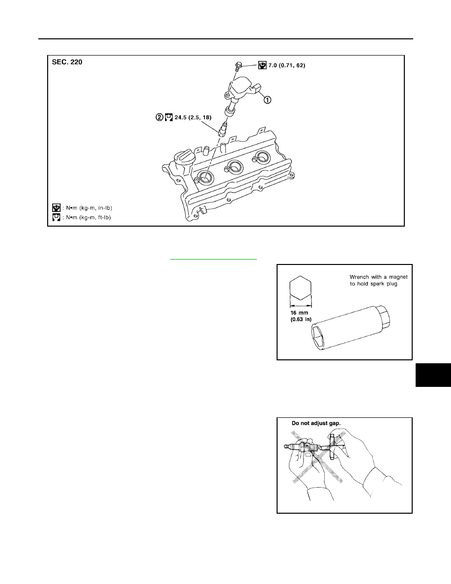
Changing Spark Plugs

ELS001OM

REMOVAL

1.

Remove the ignition coil. Refer to 

EM-32, "IGNITION COIL"

 .

2.

Remove the spark plug using a suitable tool as shown.

CAUTION:

Do not drop or shock the spark plug if reusing it.

INSPECTION AFTER REMOVAL

If plug tip is covered with carbon, spark plug cleaner may be used.

Checking and adjusting plug gap is not required between
change intervals.

1.

Ignition coil

2.

Spark plug

PBIC2901E

SEM294A

Cleaner air pressure

: Less than 588 kPa (6 kg/cm

2

 , 85 psi)

Cleaning time

: Less than 20 seconds

SMA806CA

MA-20

ENGINE MAINTENANCE

2006 Pathfinder

CAUTION:

Do not use a wire brush to clean the spark plug.

Do not drop or shock the spark plug.

INSTALLATION

Installation is in the reverse order of removal.

Use standard type spark plug for normal conditions.

The hot type spark plug is suitable when fouling occurs with the standard type spark plug under conditions
such as:

Frequent engine starts

Low ambient temperatures

The cold type spark plug is suitable when spark knock occurs with the standard type spark plug under
conditions such as:

Extended highway driving

Frequent high engine revolution

CAUTION:

Do not drop or shock the spark plug.

Checking EVAP Vapor Lines

ELS001ON

1.

Visually inspect EVAP vapor lines for improper attachment, cracks, damage, loose connections, chafing
or deterioration.

2.

Inspect vacuum relief valve of fuel tank filler cap for clogging and sticking.
Refer to 

EC-36, "How to Detect Fuel Vapor Leakage"

 .

SMA773C

Make

NGK

Standard type

PLFR5A-11

Hot type

PLFR4A-11

Cold type

PLFR6A-11

Gap (nominal)

1.1 mm (0.043 in)

CHASSIS AND BODY MAINTENANCE

MA-21

C

D

E

F

G

H

I

J

K

M

A

B

MA

2006 Pathfinder

CHASSIS AND BODY MAINTENANCE

PFP:00100

Changing the In-cabin Microfilter

ELS001OO

1.

Open the lower glove box and press in on the sides so that it will
open completely allowing it to hang by the cord.

2.

Remove the screw and remove the in-cabin microfilter cover.

3.

Remove the in-cabin microfilters from the front heater and cool-
ing unit housing.

4.

Insert the first new in-cabin microfilter into the front heater and
cooling unit housing and slide it over to the right. Insert the sec-
ond new in-cabin microfilter into the front heater and cooling unit
housing.

NOTE:
The in-cabin microfilters are marked with air flow arrows. The
end of the microfilter with the arrow should face the rear of the
vehicle. The arrows should point downward.

5.

Install the in-cabin microfilter cover.

6.

Close the lower glove box completely.

WLIA0023E

LJIA0134E

LJIA0148E

LJIA0134E

MA-22

CHASSIS AND BODY MAINTENANCE

2006 Pathfinder

Checking the Exhaust System

ELS001OP

Check exhaust pipes, muffler and mounting for improper attachment,
leaks, cracks, damage, loose connections, chafing or deterioration.

Checking the Automatic Transmission Fluid (ATF)

ELS001OQ

1.

Before driving, the ATF level can be checked at ATF tempera-
tures of 30

°

 to 50

°

 C (86

°

 to 122

°

 F) using the “COLD” range on

the ATF level gauge as follows:

a.

Park the vehicle on a level surface and set the parking brake.

b.

Start the engine and move the selector lever through each gear
position. Shift the selector lever into the “P” position.

c.

Check the ATF level with the engine idling.

d.

Remove the ATF level gauge and wipe it clean with a lint-free
paper.

CAUTION:

When wiping the ATF from the ATF level gauge, always use
a lint-free paper, not a cloth.

e.

Re-insert the ATF level gauge into the charging pipe until the
cap contacts the top of the charging pipe as shown.

CAUTION:

To check ATF level, insert the ATF level gauge until the cap
contacts the top of the charging pipe, with the gauge
reversed from the normal inserted position.

f.

Remove the ATF level gauge and note the ATF level. If the ATF
level is at low side of range, add ATF to the transmission
through the charging pipe.

CAUTION:

Do not overfill the transmission with ATF.

g.

Install the ATF level gauge and the ATF level gauge bolt.

2.

Warm up the engine and transmission.

3.

Check for any ATF leaks.

4.

Drive the vehicle to increase the ATF temperature to 80

°

 C (176

°

 F).

SMA211A

LLIA0071E

ATF level gauge bolt

: Refer to 

AT-252, "Components"

 .

SCIA1684E

CHASSIS AND BODY MAINTENANCE

MA-23

C

D

E

F

G

H

I

J

K

M

A

B

MA

2006 Pathfinder

5.

Allow the ATF temperature to fall to approximately 65

°

C (149

°

F). Use the CONSULT-II to monitor the ATF

temperature as follows:

NOTE:
The ATF level will be significantly affected by the ATF temperature as shown. Therefore monitor the ATF
temperature data using the CONSULT-II.

a.

Connect CONSULT-II to data link connector.

b.

Select “MAIN SIGNALS” in “DATA MONITOR” mode for “A/T” with CONSULT-II.

c.

Read out the value of “ATF TEMP 1”.

6.

Re-check the ATF level at ATF temperatures of approximately
65

°

C (149

°

F) using the “HOT” range on the ATF level gauge as

shown. The HOT range is between 50

°

 - 80

°

 C (122

°

 - 176

°

 F).

CAUTION:

When wiping the ATF from the ATF level gauge, always
use lint-free paper, not a cloth.

To check the ATF level, insert the ATF level gauge until
the cap contacts the top of the charging pipe, with the
gauge reversed from the normal inserted position as
shown.

7.

Check the ATF condition.

If the ATF is very dark or has some burned smell, there may
be an internal problem with the transmission. Refer to 

AT-181,

"TROUBLE DIAGNOSIS FOR SYMPTOMS"

 . Flush the trans-

mission cooling system after repairing the transmission.

If the ATF contains frictional material (clutches, bands, etc.),
replace the radiator and flush the transmission cooler lines
using cleaning solvent and compressed air after repairing the
transmission.

8.

Install the ATF level gauge in the charging pipe.

9.

Tighten the ATF level gauge bolt to specification.

SLIA0016E

LLIA0071E

ATF level gauge bolt

: Refer to 

AT-252, "Components"

 .

SCIA1684E

MA-24

CHASSIS AND BODY MAINTENANCE

2006 Pathfinder

Changing the Automatic Transmission Fluid (ATF)

ELS001OR

1.

Drive the vehicle to warm up the ATF to approximately 80

°

 C (176

°

 F).

2.

Stop the engine.

3.

Remove the ATF level gauge.

4.

Drain the ATF from the drain plug hole and then install the drain
plug with a new gasket. Refill the transmission with new ATF.
Always refill with the same volume as the drained ATF. Use the
ATF level gauge to check the ATF level as shown. Add ATF as
necessary.

To flush out the old ATF from the transmission oil coolers, pour new ATF into the charging pipe with the
engine idling and at the same time drain the old ATF from the auxiliary transmission oil cooler hose
return line.

When the color of the ATF coming out of the auxiliary transmission oil cooler hose return line is about
the same as the color of the new ATF, flushing out the old ATF is complete. The amount of new ATF
used for flushing should be 30% to 50% of the specified capacity.

CAUTION:

Use only Genuine NISSAN ATF and do not mix with other fluids.

Using automatic transmission fluid other than Genuine NISSAN ATF will cause deterioration in
driveability and automatic transmission durability, and may damage the automatic transmis-
sion, which is not covered by the warranty.

When filling the transmission with ATF, do not spill the ATF on any heat generating parts such
as the exhaust manifold.

Do not reuse the drain plug gasket.

5.

Drive the vehicle to warm up the ATF to approximately 80

°

 C (176

°

 F).

6.

Install the ATF level gauge and tighten the ATF level gauge bolt to specification.

7.

Check the fluid level and condition. If the ATF is still dirty, repeat
steps 2 through 6.

8.

Install the ATF level gauge in the charging pipe and install the ATF level gauge bolt.

9.

Tighten the ATF level gauge bolt to specification.

Drain plug

: Refer to 

AT-252, "Components"

 .

LLIA0071E

ATF type and capacity

: Refer to 

MA-11, "Fluids and Lubricants"

 .

ATF level gauge bolt

: Refer to 

AT-252, "Components"

 .

LLIA0071E

ATF level gauge bolt

: Refer to 

AT-252, "Components"

 .

CHASSIS AND BODY MAINTENANCE

MA-25

C

D

E

F

G

H

I

J

K

M

A

B

MA

2006 Pathfinder

Checking Transfer Fluid

ELS001OS

CAUTION:

If using the vehicle for towing, the transfer fluid must be replaced as specified. Refer to 

MA-7, "PERI-

ODIC MAINTENANCE"

 .

FLUID LEAKAGE AND FLUID LEVEL

1.

Make sure that fluid is not leaking from the transfer assembly or around it.

2.

Check fluid level from the filler plug hole.

CAUTION:

Do not start engine while checking fluid level.

Check the ATX14B as shown.

Check the TX15B as shown.

3.

Install the filler plug with a new gasket to the transfer. Tighten to the specified torque. Refer to 

TF-146,

"COMPONENTS"

  (ATX14B), 

TF-278, "COMPONENTS"

  (TX15B).

CAUTION:

Do not reuse gasket.

Changing Transfer Fluid

ELS001OT

CAUTION:

If using the vehicle for towing, the transfer fluid must be replaced as specified. Refer to 

MA-7, "PERI-

ODIC MAINTENANCE"

 .

DRAINING

1.

Stop engine.

2.

Remove the drain plug and gasket. Drain the fluid.

Remove the ATX14B drain plug as shown.

SDIA3209E

SDIA3287E

SDIA3208E

MA-26

CHASSIS AND BODY MAINTENANCE

2006 Pathfinder

Remove the TX15B drain plug as shown.

3.

Install the drain plug with a new gasket to the transfer. Tighten to the specified torque. Refer to 

TF-146,

"COMPONENTS"

  (ATX14B), 

TF-278, "COMPONENTS"

  (TX15B).

CAUTION:

Do not reuse gasket.

FILLING

1.

Remove the filler plug and gasket.

Check the ATX14B as shown.

Check the TX15B as shown.

2.

Fill the transfer with new fluid until the fluid level reaches the specified limit near the filler plug hole.

CAUTION:

Carefully fill fluid. (Fill up for approx. 3 minutes.)

3.

Leave the vehicle for 3 minutes, and check fluid level again.

4.

Install the filler plug with a new gasket to the transfer. Tighten to the specified torque. Refer to 

TF-146,

"COMPONENTS"

  (ATX14B), 

TF-278, "COMPONENTS"

  (TX15B).

CAUTION:

Do not reuse gasket.

Checking Propeller Shaft

ELS001OU

Check the front and rear propeller shafts for damage, dents, and cracks. Check the joints for looseness and
any damage. Repair or replace as necessary. Refer to 

PR-3, "NVH Troubleshooting Chart"

 .

SDIA3286E

SDIA3209E

SDIA3287E

Fluid grade and capacity

: Refer to 

MA-11, "Fluids and Lubricants"

 .


Content      ..     327      328      329      330     ..