Nissan Pathfinder (2006 year). Manual - part 279


  Index      Manuals     Nissan Pathfinder (2006 year) - Service and Repair Manual


Search            copyright infringement  


Content      ..     277      278      279      280     ..


Nissan Pathfinder (2006 year). Manual - part 279


INSTRUMENT PANEL ASSEMBLY

IP-13

C

D

E

F

G

H

J

K

L

M

A

B

IP

2006 Pathfinder

CLUSTER LID D

Removal

1.

Remove A/T finisher. Refer to 

IP-15, "A/T FINISHER"

 .

2.

Remove lower instrument panel LH. Refer to 

IP-14, "LOWER INSTRUMENT PANEL LH"

 .

3.

Remove lower instrument panel RH. Refer to 

IP-15, "LOWER INSTRUMENT PANEL RH AND LOWER

GLOVE BOX"

 .

4.

Remove cluster lid C. Refer to 

IP-11, "CLUSTER LID C -WITHOUT NAVIGATION SYSTEM"

 .

5.

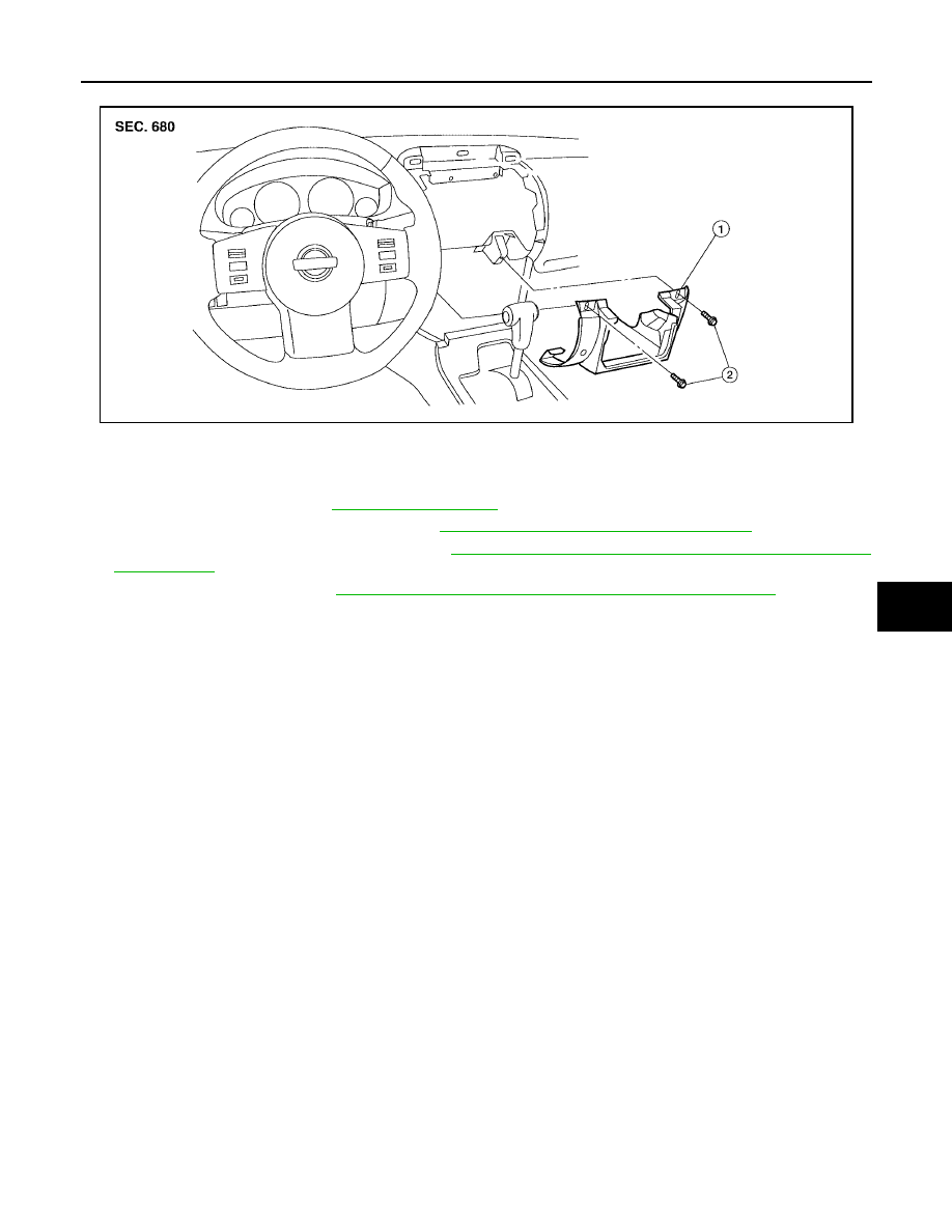
Disconnect the electrical connectors and remove cluster lid D.

Installation

Installation is in the reverse order of removal.

WIIA1052E

1.

Cluster lid D

2.

Cluster lid D screws

IP-14

INSTRUMENT PANEL ASSEMBLY

2006 Pathfinder

LOWER INSTRUMENT PANEL LH
Removal

1.

Remove front pillar lower finisher. Refer to 

EI-28, "FRONT PILLAR LOWER FINISHER"

 .

2.

Remove lower instrument panel LH, using power tool.

3.

Pull rearward to release lower instrument panel LH.

4.

Disconnect lower instrument panel LH harness connectors.

Installation

Installation is in the reverse order of removal.

COMBINATION METER

Removal

1.

Disconnect the negative battery cable.

2.

Remove front pillar upper finisher. Refer to 

EI-28, "FRONT PILLAR UPPER FINISHER"

 .

3.

Remove lower instrument panel LH. Refer to 

IP-14, "LOWER INSTRUMENT PANEL LH"

 .

4.

Remove steering lock escutcheon.

5.

Remove cluster lid A, using power tool.

6.

Remove combination meter, using power tool.

7.

Disconnect combination meter electrical connectors.

Installation

Installation is in the reverse order of removal. 

LIIA1744E

WIIA1053E

1.

Combination meter

2.

Combination meter screws

3.

Cluster lid A

4.

Ignition key lamp assembly

5.

Steering lock escutcheon

6.

Cluster lid A screws

INSTRUMENT PANEL ASSEMBLY

IP-15

C

D

E

F

G

H

J

K

L

M

A

B

IP

2006 Pathfinder

A/T FINISHER

Removal

1.

Remove cup holder finisher. 

2.

Remove A/T finisher bezel.

3.

Pull up to release clips and remove the A/T finisher.

Installation

Installation is in the reverse order of removal.

LOWER INSTRUMENT PANEL RH AND LOWER GLOVE BOX
Removal

1.

Remove front pillar lower finisher. Refer to 

EI-27, "BODY SIDE TRIM"

 .

2.

Remove lower instrument panel RH screws, using power tool.

3.

Remove lower instrument panel RH and lower glove box.

Installation

NOTE:
Install upper glove box before installing lower glove box. 
Installation is in the reverse order of removal.

UPPER GLOVE BOX
Removal

1.

Remove lower instrument panel RH and lower glove box. Refer to 

IP-15, "Removal"

 .

2.

Remove cluster lid C. Refer to 

IP-11, "CLUSTER LID C -WITHOUT NAVIGATION SYSTEM"

 .

3.

Remove upper glove box screws, using power tool.

4.

Remove upper glove box.

Installation

Installation is in the reverse order of removal.

WIIA1054E

1.

Cluster lid D

2.

A/T finisher

3.

Cup holder finisher

4.

Center console front base

Front

IP-16

INSTRUMENT PANEL ASSEMBLY

2006 Pathfinder

CENTER CONSOLE

Removal

1.

Remove lower instrument panel RH. Refer to 

IP-15, "LOWER INSTRUMENT PANEL RH AND LOWER

GLOVE BOX"

 .

2.

Remove cup holder finisher.

3.

Remove A/T finisher. Refer to 

IP-15, "A/T FINISHER"

 .

4.

Remove center console screws.

5.

Disconnect electrical connectors and remove center console.

Installation

Installation is in the reverse order of removal.

WIIA1058E

INSTRUMENT PANEL ASSEMBLY

IP-17

C

D

E

F

G

H

J

K

L

M

A

B

IP

2006 Pathfinder

Disassembly and Assembly

EIS008IC

LOWER GLOVE BOX

Disassembly

1.

Remove fuse block cover.

2.

Remove damper hook.

3.

Remove lower glove box latch cover. 

4.

Remove lower glove box latch assembly.

Assembly

Assembly is in the reverse order of disassembly.

UPPER GLOVE BOX
Disassembly

1.

Remove upper glove box door screws.

2.

Remove upper glove box door.

Assembly

Assembly is in the reverse order of disassembly.

1.

Upper glove box

2.

Upper glove box door

3.

Lower instrument panel RH

4.

Fuse block cover

5.

Lower glove box latch assembly cover 6.

Lower glove box

7.

Lower glove box latch assembly

8.

Damper hook

9.

Lower glove box damper

WIIA1049E

IP-18

INSTRUMENT PANEL ASSEMBLY

2006 Pathfinder

CENTER CONSOLE

Disassembly

1.

Remove center console. Refer to 

IP-16, "CENTER CONSOLE"

 .

2.

Remove center console lid.

3.

Remove latch from center console lid.

4.

Remove hinge from center console lid.

5.

Remove rear finisher assembly.

6.

Remove rear cup holder assembly.

7.

Remove DVD player, if equipped.

8.

Disconnect center console harness connectors.

9.

Remove cup holder insert and cup holder assembly.

10. Remove center console bin.
11. Remove center console bracket.

12. Remove wire harness bracket.

LIIA1749E

1.

Cup holder assembly

2.

Cup holder insert

3.

Center console bin

4.

Center console lid

5.

Hinge

6.

Ventilator console grille

7.

Rear cup holder assembly

8.

Rear finisher assembly

9.

Wire harness bracket

10.

Bracket DVD

11.

Center console rear base

12.

Bracket

13.

Cup holder finisher 

14.

Center console front base

15.

A/T finisher bezel

16.

A/T finisher

17.

Ash tray

18.

Switch assembly

19.

Switch finisher

20.

CD changer door

21.

Console bin

INSTRUMENT PANEL ASSEMBLY

IP-19

C

D

E

F

G

H

J

K

L

M

A

B

IP

2006 Pathfinder

Assembly

Assembly is in the reverse order of disassembly.

IP-20

INSTRUMENT PANEL ASSEMBLY

2006 Pathfinder


Content      ..     277      278      279      280     ..