Nissan Pathfinder (2006 year). Manual - part 261


  Index      Manuals     Nissan Pathfinder (2006 year) - Service and Repair Manual


Search            copyright infringement  


Content      ..     259      260      261      262     ..


Nissan Pathfinder (2006 year). Manual - part 261


SERVICE INFORMATION FOR ELECTRICAL INCIDENT

GI-25

C

D

E

F

G

H

I

J

K

L

M

B

GI

2006 Pathfinder

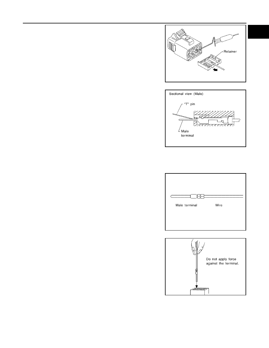
Some connectors do not have a notch above each terminal. To
probe each terminal, remove the connector retainer to make
contact space for probing.

MALE TERMINAL
Carefully probe the contact surface of each terminal using a “T” pin.
Do not bend terminal.

How to Check Enlarged Contact Spring of Terminal 

An enlarged contact spring of a terminal may create intermittent signals in the circuit.
If the intermittent open circuit occurs, follow the procedure below to inspect for open wires and enlarged con-
tact spring of female terminal.
1.

Assemble a male terminal and approx. 10 cm (3.9 in) of wire.
Use a male terminal which matches the female terminal.

2.

Disconnect the suspected faulty connector and hold it terminal
side up.

3.

While holding the wire of the male terminal, try to insert the male
terminal into the female terminal.
Do not force the male terminal into the female terminal with
your hands.

SEL266V

SEL267V

SEL270V

SEL271V

GI-26

SERVICE INFORMATION FOR ELECTRICAL INCIDENT

2006 Pathfinder

4.

While moving the connector, check whether the male terminal
can be easily inserted or not.

If the male terminal can be easily inserted into the female termi-
nal, replace the female terminal.

Waterproof Connector Inspection 

If water enters the connector, it can short interior circuits. This may lead to intermittent problems.
Check the following items to maintain the original waterproof characteristics.

RUBBER SEAL INSPECTION

Most waterproof connectors are provided with a rubber seal
between the male and female connectors. If the seal is missing,
the waterproof performance may not meet specifications.

The rubber seal may come off when connectors are discon-
nected. Whenever connectors are reconnected, make sure the
rubber seal is properly installed on either side of male or female
connector.

WIRE SEAL INSPECTION
The wire seal must be installed on the wire insertion area of a waterproof connector. Be sure that the seal is
installed properly.

Terminal Lock Inspection 

Check for unlocked terminals by pulling wire at the end of connector.
An unlocked terminal may create intermittent signals in the circuit.

SEL272V

SEL273V

SEL275V

SEL330V

SERVICE INFORMATION FOR ELECTRICAL INCIDENT

GI-27

C

D

E

F

G

H

I

J

K

L

M

B

GI

2006 Pathfinder

How to Perform Efficient Diagnosis for an Electrical Incident

EAS001S0

WORK FLOW

INCIDENT SIMULATION TESTS 
Introduction 

Sometimes the symptom is not present when the vehicle is brought in for service. If possible, re-create the
conditions present at the time of the incident. Doing so may help avoid a No Trouble Found Diagnosis. The fol-
lowing section illustrates ways to simulate the conditions/environment under which the owner experiences an
electrical incident.
The section is broken into the six following topics:

Vehicle vibration

Heat sensitive

SGI838

STEP

DESCRIPTION

STEP 1

Get detailed information about the conditions and the environment when the incident occurred.
The following are key pieces of information required to make a good analysis:

WHAT

Vehicle Model, Engine, Transmission/Transaxle and the System (i.e. Radio).

WHEN

Date, Time of Day, Weather Conditions, Frequency.

WHERE

Road Conditions, Altitude and Traffic Situation.

HOW

System Symptoms, Operating Conditions (Other Components Interaction). 
Service History and if any After Market Accessories have been installed. 

STEP 2

Operate the system, road test if necessary.
Verify the parameter of the incident.
If the problem cannot be duplicated, refer to “Incident Simulation Tests”.

STEP 3

Get the proper diagnosis materials together including:

Power Supply Routing

System Operation Descriptions

Applicable Service Manual Sections

Check for any Service Bulletins

Identify where to begin diagnosis based upon your knowledge of the system operation and the customer comments.

STEP 4

Inspect the system for mechanical binding, loose connectors or wiring damage.
Determine which circuits and components are involved and diagnose using the Power Supply Routing and Harness 
Layouts.

STEP 5

Repair or replace the incident circuit or component.

STEP 6

Operate the system in all modes. Verify the system works properly under all conditions. Make sure you have not inad-
vertently created a new incident during your diagnosis or repair steps.

GI-28

SERVICE INFORMATION FOR ELECTRICAL INCIDENT

2006 Pathfinder

Freezing

Water intrusion

Electrical load

Cold or hot start up

Get a thorough description of the incident from the customer. It is important for simulating the conditions of the
problem.

Vehicle Vibration 

The problem may occur or become worse while driving on a rough road or when engine is vibrating (idle with
A/C on). In such a case, you will want to check for a vibration related condition. Refer to the following illustra-
tion.

CONNECTORS & HARNESS
Determine which connectors and wiring harness would affect the electrical system you are inspecting. Gently
shake each connector and harness while monitoring the system for the incident you are trying to duplicate.
This test may indicate a loose or poor electrical connection.

HINT
Connectors can be exposed to moisture. It is possible to get a thin film of corrosion on the connector termi-
nals. A visual inspection may not reveal this without disconnecting the connector. If the problem occurs inter-
mittently, perhaps the problem is caused by corrosion. It is a good idea to disconnect, inspect and clean the
terminals on related connectors in the system.

SENSORS & RELAYS
Gently
 apply a slight vibration to sensors and relays in the system you are inspecting.
This test may indicate a loose or poorly mounted sensor or relay.

ENGINE COMPARTMENT
There are several reasons a vehicle or engine vibration could cause an electrical complaint. Some of the
things to check for are:

Connectors not fully seated.

Wiring harness not long enough and is being stressed due to engine vibrations or rocking.

Wires laying across brackets or moving components.

Loose, dirty or corroded ground wires.

Wires routed too close to hot components.

To inspect components under the hood, start by verifying the integrity of ground connections. (Refer to Ground
Inspection described later.) First check that the system is properly grounded. Then check for loose connection
by gently shaking the wiring or components as previously explained. Using the wiring diagrams inspect the
wiring for continuity.

BEHIND THE INSTRUMENT PANEL
An improperly routed or improperly clamped harness can become pinched during accessory installation. Vehi-
cle vibration can aggravate a harness which is routed along a bracket or near a screw.

UNDER SEATING AREAS

SGI839

SERVICE INFORMATION FOR ELECTRICAL INCIDENT

GI-29

C

D

E

F

G

H

I

J

K

L

M

B

GI

2006 Pathfinder

An unclamped or loose harness can cause wiring to be pinched by seat components (such as slide guides)
during vehicle vibration. If the wiring runs under seating areas, inspect wire routing for possible damage or
pinching.

Heat Sensitive 

The customer's concern may occur during hot weather or after car
has sat for a short time. In such cases you will want to check for a
heat sensitive condition.
To determine if an electrical component is heat sensitive, heat the
component with a heat gun or equivalent.
Do not heat components above 60

°

C (140

°

F). If incident occurs

while heating the unit, either replace or properly insulate the compo-
nent.

Freezing 

The customer may indicate the incident goes away after the car
warms up (winter time). The cause could be related to water freezing
somewhere in the wiring/electrical system.
There are two methods to check for this. The first is to arrange for
the owner to leave his car overnight. Make sure it will get cold
enough to demonstrate his complaint. Leave the car parked outside
overnight. In the morning, do a quick and thorough diagnosis of
those electrical components which could be affected.
The second method is to put the suspect component into a freezer
long enough for any water to freeze. Reinstall the part into the car
and check for the reoccurrence of the incident. If it occurs, repair or
replace the component.

Water Intrusion 

The incident may occur only during high humidity or in rainy/snowy
weather. In such cases the incident could be caused by water intru-
sion on an electrical part. This can be simulated by soaking the car
or running it through a car wash.
Do not spray water directly on any electrical components.

Electrical Load 

The incident may be electrical load sensitive. Perform diagnosis with
all accessories (including A/C, rear window defogger, radio, fog
lamps) turned on.

Cold or Hot Start Up 

On some occasions an electrical incident may occur only when the car is started cold, or it may occur when
the car is restarted hot shortly after being turned off. In these cases you may have to keep the car overnight to
make a proper diagnosis.

SGI842

SGI843

SGI844

SGI845

GI-30

SERVICE INFORMATION FOR ELECTRICAL INCIDENT

2006 Pathfinder

CIRCUIT INSPECTION 
Introduction 

In general, testing electrical circuits is an easy task if it is approached in a logical and organized method.
Before beginning it is important to have all available information on the system to be tested. Also, get a thor-
ough understanding of system operation. Then you will be able to use the appropriate equipment and follow
the correct test procedure.
You may have to simulate vehicle vibrations while testing electrical components. Gently shake the wiring har-
ness or electrical component to do this.

NOTE:
Refer to “How to Check Terminal”  to probe or check terminal.

Testing for “Opens” in the Circuit 

Before you begin to diagnose and test the system, you should rough sketch a schematic of the system. This
will help you to logically walk through the diagnosis process. Drawing the sketch will also reinforce your work-
ing knowledge of the system.

CONTINUITY CHECK METHOD
The continuity check is used to find an open in the circuit. The digital multimeter (DMM) set on the resistance
function will indicate an open circuit as over limit (no beep tone or no ohms symbol). Make sure to always start
with the DMM at the highest resistance level. 
To help in understanding the diagnosis of open circuits, please refer to the previous schematic.

Disconnect the battery negative cable.

Start at one end of the circuit and work your way to the other end. (At the fuse block in this example)

Connect one probe of the DMM to the fuse block terminal on the load side.

Connect the other probe to the fuse block (power) side of SW1. Little or no resistance will indicate that
portion of the circuit has good continuity. If there were an open in the circuit, the DMM would indicate an
over limit or infinite resistance condition. (point A)

Connect the probes between SW1 and the relay. Little or no resistance will indicate that portion of the cir-
cuit has good continuity. If there were an open in the circuit, the DMM would indicate an over limit or infi-
nite resistance condition. (point B)

Connect the probes between the relay and the solenoid. Little or no resistance will indicate that portion of
the circuit has good continuity. If there were an open in the circuit, the DMM would indicate an over limit or
infinite resistance condition. (point C)

Any circuit can be diagnosed using the approach in the previous example.

VOLTAGE CHECK METHOD
To help in understanding the diagnosis of open circuits please refer to the previous schematic.
In any powered circuit, an open can be found by methodically checking the system for the presence of voltage.
This is done by switching the DMM to the voltage function.

OPEN

A circuit is open when there is no continuity through a section of the circuit.

SHORT

There are two types of shorts.

SHORT CIRCUIT

When a circuit contacts another circuit and causes the normal resistance to 
change.

SHORT TO GROUND

When a circuit contacts a ground source and grounds the circuit.

SGI846-A

SERVICE INFORMATION FOR ELECTRICAL INCIDENT

GI-31

C

D

E

F

G

H

I

J

K

L

M

B

GI

2006 Pathfinder

Connect one probe of the DMM to a known good ground.

Begin probing at one end of the circuit and work your way to the other end.

With SW1 open, probe at SW1 to check for voltage.
voltage; open is further down the circuit than SW1.
no voltage; open is between fuse block and SW1 (point A).

Close SW1 and probe at relay.
voltage; open is further down the circuit than the relay.
no voltage; open is between SW1 and relay (point B).

Close the relay and probe at the solenoid.
voltage; open is further down the circuit than the solenoid.
no voltage; open is between relay and solenoid (point C).

Any powered circuit can be diagnosed using the approach in the previous example.

Testing for “Shorts” in the Circuit 

To simplify the discussion of shorts in the system, please refer to the following schematic.

RESISTANCE CHECK METHOD

Disconnect the battery negative cable and remove the blown fuse.

Disconnect all loads (SW1 open, relay disconnected and solenoid disconnected) powered through the
fuse.

Connect one probe of the DMM to the load side of the fuse terminal. Connect the other probe to a known
good ground.

With SW1 open, check for continuity.
continuity; short is between fuse terminal and SW1 (point A).
no continuity; short is further down the circuit than SW1.

Close SW1 and disconnect the relay. Put probes at the load side of fuse terminal and a known good
ground. Then, check for continuity.
continuity; short is between SW1 and the relay (point B).
no continuity; short is further down the circuit than the relay.

Close SW1 and jump the relay contacts with jumper wire. Put probes at the load side of fuse terminal and
a known good ground. Then, check for continuity.
continuity; short is between relay and solenoid (point C).
no continuity; check solenoid, retrace steps.

VOLTAGE CHECK METHOD

Remove the blown fuse and disconnect all loads (i.e. SW1 open, relay disconnected and solenoid discon-
nected) powered through the fuse.

Turn the ignition key to the ON or START position. Verify battery voltage at the battery + side of the fuse
terminal (one lead on the battery + terminal side of the fuse block and one lead on a known good ground).

With SW1 open and the DMM leads across both fuse terminals, check for voltage.
voltage; short is between fuse block and SW1 (point A).
no voltage; short is further down the circuit than SW1.

With SW1 closed, relay and solenoid disconnected and the DMM leads across both fuse terminals, check
for voltage.
voltage; short is between SW1 and the relay (point B).

SGI847-A

GI-32

SERVICE INFORMATION FOR ELECTRICAL INCIDENT

2006 Pathfinder

no voltage; short is further down the circuit than the relay.

With SW1 closed, relay contacts jumped with fused jumper wire check for voltage.
voltage; short is down the circuit of the relay or between the relay and the disconnected solenoid (point C).
no voltage; retrace steps and check power to fuse block.

Ground Inspection 

Ground connections are very important to the proper operation of electrical and electronic circuits. Ground
connections are often exposed to moisture, dirt and other corrosive elements. The corrosion (rust) can
become an unwanted resistance. This unwanted resistance can change the way a circuit works.
Electronically controlled circuits are very sensitive to proper grounding. A loose or corroded ground can drasti-
cally affect an electronically controlled circuit. A poor or corroded ground can easily affect the circuit. Even
when the ground connection looks clean, there can be a thin film of rust on the surface.
When inspecting a ground connection follow these rules:

Remove the ground bolt or screw.

Inspect all mating surfaces for tarnish, dirt, rust, etc.

Clean as required to assure good contact.

Reinstall bolt or screw securely.

Inspect for “add-on” accessories which may be interfering with the ground circuit.

If several wires are crimped into one ground eyelet terminal, check for proper crimps. Make sure all of the
wires are clean, securely fastened and providing a good ground path. If multiple wires are cased in one
eyelet make sure no ground wires have excess wire insulation.

For detailed ground distribution information, refer to “Ground Distribution” in PG section.

Voltage Drop Tests 

Voltage drop tests are often used to find components or circuits which have excessive resistance. A voltage
drop in a circuit is caused by a resistance when the circuit is in operation.
Check the wire in the illustration. When measuring resistance with DMM, contact by a single strand of wire will
give reading of 0 ohms. This would indicate a good circuit. When the circuit operates, this single strand of wire
is not able to carry the current. The single strand will have a high resistance to the current. This will be picked
up as a slight voltage drop. 
Unwanted resistance can be caused by many situations as follows:

Undersized wiring (single strand example)

Corrosion on switch contacts

Loose wire connections or splices.

If repairs are needed always use wire that is of the same or larger gauge.

MEASURING VOLTAGE DROP  —  ACCUMULATED METHOD

SGI853


Content      ..     259      260      261      262     ..