Nissan Pathfinder (2006 year). Manual - part 251


  Index      Manuals     Nissan Pathfinder (2006 year) - Service and Repair Manual


Search            copyright infringement  


Content      ..     249      250      251      252     ..


Nissan Pathfinder (2006 year). Manual - part 251


WHEEL HUB

FAX-5

C

E

F

G

H

I

J

K

L

M

A

B

FAX

2006 Pathfinder

WHEEL HUB

PFP:43202

On-Vehicle Inspection and Service

EDS003AB

Make sure the mounting conditions (looseness, backlash) of each component and component status (wear,
damage) are normal.

WHEEL BEARING INSPECTION

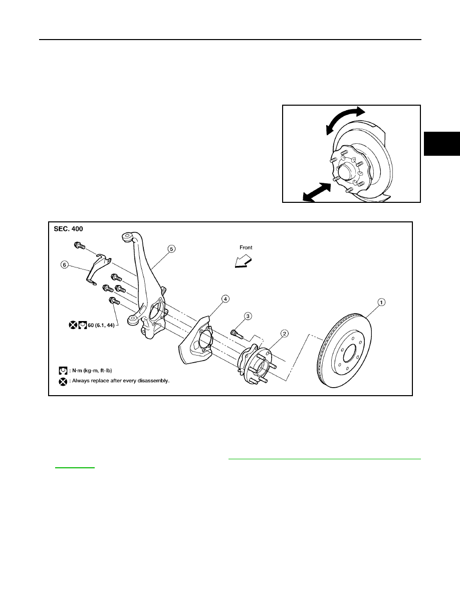
Move wheel hub in the axial direction by hand. Make sure there
is no looseness of wheel bearing.

Rotate wheel hub and make sure there is no unusual noise or
other irregular conditions. If there are any irregular conditions,
replace wheel hub and bearing assembly.

Removal and Installation

EDS003AC

REMOVAL

1.

Remove wheel and tire using power tool.

2.

Without disassembling the hydraulic lines, remove caliper torque member bolts using power tool. Then
reposition brake caliper aside with wire. Refer to 

BR-25, "Removal and Installation of Brake Caliper and

Disc Rotor"

 .

CAUTION:

Do not press brake pedal while brake caliper is removed.

Axial end play limit 

: 0.05 mm (0.002 in) or less

SMA571A

1.

Disc rotor

2.

Wheel hub and bearing assembly

3.

Wheel stud

4.

Splash guard

5.

Steering knuckle

6.

Wheel sensor bracket

WDIA0228E

FAX-6

WHEEL HUB

2006 Pathfinder

3.

Put alignment mark on disc rotor and wheel hub and bearing
assembly, then remove disc rotor.

4.

Remove cotter pin, then remove lock nut from drive shaft using power tool. Refer to 

FAX-7, "Removal and

Installation"

 .

5.

Remove drive shaft from wheel hub and bearing assembly. Refer to 

FAX-7, "Removal and Installation"

 .

6.

Remove wheel sensor from wheel hub and bearing assembly. Refer to 

BRC-60, "Removal and Installa-

tion"

 .

Inspect the wheel sensor O-ring, replace the wheel sensor assembly if damaged.

Clean the wheel sensor hole and mounting surface with a suitable brake cleaner and clean lint-free
shop rag. Be careful that dirt and debris do not enter the axle bearing area.

Apply a coat of suitable grease to the wheel sensor O-ring and mounting hole.

CAUTION:

Do not pull on the wheel sensor harness.

7.

Remove wheel hub and bearing assembly bolts using power tool.

8.

Remove splash guard and wheel hub and bearing assembly from steering knuckle.

Carefully remove wheel sensor and harness through hole in splash guard.

INSPECTION AFTER REMOVAL

Check for deformity, cracks and damage on each part and replace if necessary.

INSTALLATION

Installation is in the reverse order of removal.

Use new bolts when installing the wheel hub and bearing assembly.

When installing disc rotor on wheel hub and bearing assembly,
position the disc rotor according to alignment mark.
(When not using the alignment mark, refer to 

BR-25, "Removal

and Installation of Brake Caliper and Disc Rotor"

 .)

When installing wheel and tire, refer to 

WT-7, "Rotation"

 .

WDIA0044E

WDIA0044E

DRIVE SHAFT

FAX-7

C

E

F

G

H

I

J

K

L

M

A

B

FAX

2006 Pathfinder

DRIVE SHAFT

PFP:39100

Removal and Installation

EDS003AD

REMOVAL 

1.

Remove wheel and tire using power tool.

2.

Remove rear engine under cover using power tool.

3.

Remove wheel sensor harness from mount on knuckle, then disconnect wheel sensor harness connector.

CAUTION:

Do not pull on wheel sensor harness.

4.

Remove wheel hub and bearing assembly. Refer to 

FAX-5, "Removal and Installation"

 .

It is not necessary to remove wheel sensor from wheel hub when wheel hub is not being replaced.

Carefully feed wheel sensor harness through hole in splash shield.

5.

Separate upper link ball joint stud from steering knuckle using
Tool.

Support lower link with jack.

6.

Remove drive shaft assembly.

Pry drive shaft front final drive using suitable tool.

INSPECTION AFTER REMOVAL

Move joint up, down, left, right, and in axial direction. Check for any rough movement or significant loose-
ness.

Check boot for cracks or other damage, and for grease leakage.

If damaged, disassemble drive shaft to verify damage, and
repair or replace as necessary.

1.

Differential side oil seal

2.

Drive shaft

3.

Drive shaft lock nut

4.

Cotter pin

WDIA0341E

Tool number

: ST29020001 (J-24319-01)

WEIA0119E

SFA108A

FAX-8

DRIVE SHAFT

2006 Pathfinder

INSTALLATION

Installation is in the reverse order of removal.

When installing drive shaft onto front final drive, use Tool to pre-
vent damage to the oil seal while inserting drive shaft. Slide
drive shaft sliding joint and tap with a hammer to install securely.

CAUTION:

Never reuse the differential side oil seal.

Tighten wheel nuts to specification. Refer to 

WT-7, "Rotation"

 .

Disassembly and Assembly

EDS003AE

DISASSEMBLY
Final Drive Side

1.

Mount the drive shaft in a vise.

CAUTION:

When mounting the drive shaft in a vise, use copper or aluminum plates between the vise and the
drive shaft.

2.

Remove boot bands and slide the boot back.

3.

Put matching marks on housing and shaft before separating joint assembly.

CAUTION:

Use paint or similar substance for matching marks. Do not scratch the surfaces.

Tool number

: KV38105500 (J-33904)

SDIA2615E

1.

Circlip

2.

Dust cover

3.

Housing

4.

Snap ring

5.

Ball cage, steel ball and inner race assembly

6.

Stopper ring

7.

Boot band

8.

Boot

9.

Shaft

10.

Joint sub-assembly

WDIA0342E

DRIVE SHAFT

FAX-9

C

E

F

G

H

I

J

K

L

M

A

B

FAX

2006 Pathfinder

4.

Remove the stopper ring with a flat-bladed screwdriver as
shown, and pull the housing off.

5.

Remove the snap ring, then remove the ball cage, steel ball,
inner race assembly from the shaft.

6.

Remove the boot from the shaft.

7.

Remove circlip and dust cover from housing.

8.

Clean the old grease off of the housing using paper towels.

Wheel Side

1.

Mount the drive shaft in a vise.

CAUTION:

When mounting the drive shaft in a vise, use copper or aluminum plates between the vise and the
drive shaft.

2.

Remove the boot bands and slide the boot back.

3.

Screw a sliding hammer or suitable tool 30 mm (1.18 in) or more
into threaded part of joint sub-assembly. Pull joint sub-assembly
off of shaft as shown.

NOTE:
Align the sliding hammer and shaft and remove the joint sub-
assembly by pulling directly.

CAUTION:

If the joint sub-assembly cannot be removed after five or
more unsuccessful attempts, replace the entire drive
shaft assembly.

4.

Remove boot from the shaft.

5.

Remove circlip from the shaft.

6.

While rotating the ball cage, clean the old grease off of the joint sub-assembly using paper towels.

INSPECTION AFTER DISASSEMBLY
Shaft

Replace the shaft if there is any bending, cracking, or other damage.

Joint Sub-assembly

Check for any rough rotation or unusual axial looseness.

Clean any foreign material from inside the joint sub-assembly.

Check for any compression scars, cracks, or fractures.

CAUTION:

If any irregular conditions are found in the joint sub-assembly components, replace the entire joint
sub-assembly.

SFA476

SFA514A

SDIA0606E

FAX-10

DRIVE SHAFT

2006 Pathfinder

Housing

NOTE:
Housing, ball cage, steel ball, and inner race are in a set.

Check for any compression scars, cracks, fractures, or unusual wear on the ball rolling surface.

Check for any deformation of the boot installation components.

Ball Cage

Check the sliding surface for any compression scars, cracks, or fractures of sliding surface.

Steel Ball

Check for any compression scars, cracks, fractures, or unusual wear.

Inner Race

Check the ball sliding surface for any compression scars, cracks, or fractures.

Check for any damage to the serrated part.

ASSEMBLY
Final Drive Side

1.

Wrap the serrated part of the shaft with tape. Install the boot
band and boot to shaft.

NOTE:
Discard the old boot band and boot and use a new one for
assembly.

2.

Remove the tape wound around the serrated part of the shaft.

3.

Install the ball cage, steel ball, and inner race assembly on the
shaft, and secure them using the snap ring.

NOTE:
Discard the old snap ring and use a new one for assembly.

4.

Insert the specified quantity of Genuine NISSAN Grease or
equivalent, into the housing (indicated by * marks), and install it
onto shaft. Refer to 

MA-11, "RECOMMENDED FLUIDS AND

LUBRICANTS"

 .

5.

Install the stopper ring onto the housing.

CAUTION:

Do not reuse stopper rings.

Make sure that housing and stopper ring are fully engaged.

SFA800

SDIA1125E

Grease capacity

: 120 

 140 g (4.23 

 4.94 oz)

SDIA1446E

DRIVE SHAFT

FAX-11

C

E

F

G

H

I

J

K

L

M

A

B

FAX

2006 Pathfinder

6.

Install the boot securely into the grooves (indicated by * marks)
as shown.

CAUTION:

If there is grease on boot mounting surfaces (indicated by *
marks) of shaft and housing, boot may come off. Remove
all grease from surfaces.

7.

Check that the boot installation length “L” is the length indicated
below. Insert a flat-tip screwdriver or similar tool into the large
side of boot. Bleed air from boot to prevent boot deformation.

CAUTION:

The boot may break if the boot installation length is less than the specified value.

Do not to touch the tip of the screwdriver to the inside of the boot.

8.

Secure the big and small ends of the boot with the new boot
bands as shown. 

NOTE:
Discard not reuse boot bands.

9.

Secure housing and shaft and then make sure that they are in the correct position when rotating boot. Use
a new boot band if the boot band needs to be loosened to reposition the boot.

10. Install circlip and dust cover to housing.

NOTE:
Do not reuse circlip and dust cover.

Wheel Side

1.

Insert the Genuine NISSAN Grease or equivalent, into the joint
sub-assembly serration hole until the grease begins to ooze
from the ball groove and serration hole. Refer to 

MA-11, "REC-

OMMENDED FLUIDS AND LUBRICANTS"

 . After inserting the

grease, use a shop cloth to wipe off the grease that has oozed
out.

2.

Wrap the serrated part of the shaft with tape. Install the boot
band and boot onto the shaft. Do not damage the boot.

NOTE:
Discard the old boot band and boot and use a new one for
assembly.

3.

Remove the protective tape wound around the serrated part of
the shaft.

Boot installation length “L ”

: 163.9 - 164.3 mm 
(6.45 - 6.47 in)

SDIA2493E

SFA395

SDIA1127E

SFA800

FAX-12

DRIVE SHAFT

2006 Pathfinder

4.

Attach the circlip to the shaft. The circlip must fit securely into
the shaft groove. Attach the nut to the joint sub-assembly.
Use a soft hammer to press-fit the circlip.

NOTE:
Discard the old circlip and use a new one for assembly.

5.

Insert the specified quantity of Genuine NISSAN Grease or
equivalent, into the joint sub-assembly and the large end of the
boot. Refer to 

MA-11, "RECOMMENDED FLUIDS AND LUBRI-

CANTS"

 .

6.

Install the boot securely into the grooves (indicated by the *
marks) as shown.

CAUTION:

If there is grease on the boot mounting surfaces (indicated
by the * marks) of the shaft and joint sub-assembly, the
boot may come off. Remove all grease from the drive shaft
surfaces. 

7.

Check that the boot installation length “L” is the specified length.
Insert a flat-tip screwdriver or similar tool into the large side of
the boot. Bleed the air from the boot to prevent boot deforma-
tion. 

CAUTION:

The boot may break if the boot installation length is less than the specified length.

Do not contact inside surface of boot with the tip of the screwdriver.

8.

Secure large and small ends of the boot using new boot bands
using a boot band crimping tool as shown.

NOTE:
Do not reuse boot bands.

Secure boot band so that dimension "M" meets specification
as shown.

9.

After installing the housing to the shaft, rotate the boot to check
that it is positioned correctly. If the boot is not positioned cor-
rectly, remove the old boot bands then reposition the boot and
secure the boot with new boot bands.

Grease capacity

: 115 

 135 g (4.01 

 4.76 oz)

RAC0049D

Boot installation length “L”

: 135.1 mm (5.32 in)

Tool number

: KV40107300 (

)

SDIA2493E

RAC1133D

Dimension "M"

: 1.0 – 4.0 mm (0.39 – 1.57 in)

DSF0047D


Content      ..     249      250      251      252     ..