Nissan Pathfinder (2006 year). Manual - part 144
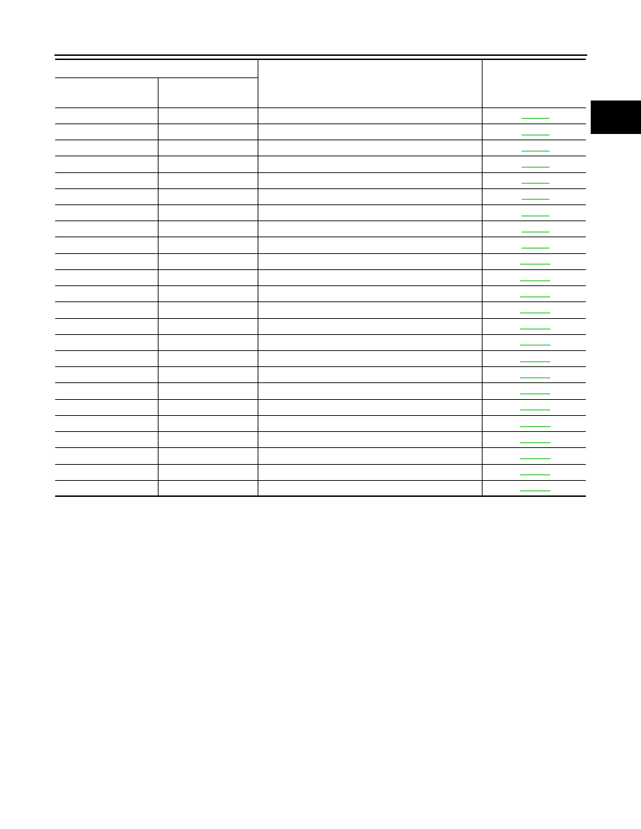
INDEX FOR DTC
EC-11
C
D
E
F
G
H
I
J
K
L
M
A
EC
2006 Pathfinder
*1: 1st trip DTC No. is the same as DTC No.
*2: This number is prescribed by SAE J2012.
*3: In Diagnostic Test Mode II (Self-diagnostic results), this number is controlled by NISSAN.
*4: The troubleshooting for this DTC needs CONSULT-II.
*5: When the fail-safe operations for both self-diagnoses occur, the MIL illuminates.
P1754
1754
I/C SOLENOID FNCTN
P1757
1757
FR/B SOLENOID/CIRC
P1759
1759
FR/B SOLENOID FNCT
P1762
1762
D/C SOLENOID/CIRC
P1764
1764
D/C SOLENOID FNCTN
P1767
1767
HLR/C SOL/CIRC
P1769
1769
HLR/C SOL FNCTN
P1772
1772
LC/B SOLENOID/CIRC
P1774
1774
LC/B SOLENOID FNCT
P1800
1800
VIAS S/V CIRC
P1805
1805
BRAKE SW/CIRCUIT
P2100
2100
ETC MOT PWR
P2101
2101
ETC FUNCTION/CIRC
P2103
2103
ETC MOT PWR
P2118
2118
ETC MOT
P2119
2119
ETC ACTR
P2122
2122
APP SEN 1/CIRC
P2123
2123
APP SEN 1/CIRC
P2127
2127
APP SEN 2/CIRC
P2128
2128
APP SEN 2/CIRC
P2135
2135
TP SENSOR
P2138
2138
APP SENSOR
P2A00
2A00
A/F SEN1 (B1)
P2A03
2A03
A/F SEN1 (B2)
DTC*
1
Items
(CONSULT-II screen terms)
Reference page
CONSULT-II
GST*
2
ECM*
3