Nissan Pathfinder (2006 year). Manual - part 142


  Index      Manuals     Nissan Pathfinder (2006 year) - Service and Repair Manual


Search            copyright infringement  


Content      ..     140      141      142      143     ..


Nissan Pathfinder (2006 year). Manual - part 142


WARNING CHIME

DI-57

C

D

E

F

G

H

I

J

L

M

A

B

DI

2006 Pathfinder

5. 

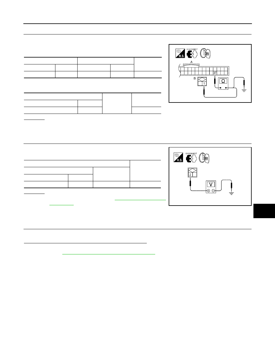
CHECK KEY SWITCH CIRCUIT 

1.

Disconnect BCM connector M18.

2.

Check continuity between BCM harness connector M18 (A) ter-
minal 37 and key switch harness connector M27 (B) terminal 1.

3.

Check continuity between BCM harness connector M18 (A) ter-
minal 37 and ground.

OK or NG

OK

>> GO TO 6.

NG

>> Repair harness or connector.

6. 

CHECK KEY SWITCH POWER SUPPLY CIRCUIT

Check voltage between key switch harness connector M27 terminal
2 and ground.

OK or NG

OK

>> Replace the BCM. Refer to 

BCS-27, "Removal and

Installation"

 .

NG

>> Check harness for open between fuse and key switch.

Light Warning Chime Does Not Operate

EKS00FZ4

1. 

CHECK WARNING CHIME OPERATION

Check key warning chime and seat belt warning chime functions.

Do key warning chime and seat belt warning chime sound?

YES

>> GO TO 2.

NO

>> Go to 

DI-53, "All Warning Chimes Do Not Operate"

 .

A

B

Continuity

Connector

Terminal

Connector

Terminal

BCM: M18

37

Key switch: M27

1

Yes

A

Ground

Continuity

Connector

Terminal

BCM: M18

37

No

WKIA4102E

Terminals

Voltage 

(Approx.)

(+)

(-)

Key switch connector

Terminal

M27

2

Ground

Battery voltage

WKIA4103E

DI-58

WARNING CHIME

2006 Pathfinder

2. 

CHECK BCM INPUT SIGNAL

With CONSULT-II

1.

Select "BCM".

2.

With "DATA MONITOR" of "BUZZER", confirm "LIGHT SW 1ST"
status changes when the lighting switch is moved from ON (1st
position) to OFF.

Without CONSULT-II

Check combination switch. Refer to 

LT-80, "Combination Switch

Reading Function"

 .

OK or NG

OK

>> Replace the BCM. Refer to 

BCS-27, "Removal and

Installation"

 .

NG

>> Check lighting switch. Refer to 

LT-80, "Combination Switch Reading Function"

 .

Seat Belt Warning Chime Does Not Operate

EKS00FZ5

1. 

CHECK WARNING CHIME OPERATION

1.

With key removed from the ignition and the front door LH open, turn the lighting switch to 1st or 2nd posi-
tion.

2.

Return lighting switch to OFF position, and insert key into ignition.

Does warning chime sound for both steps?

YES

>> GO TO 2.

NO

>> Go to 

DI-53, "All Warning Chimes Do Not Operate"

 .

2. 

CHECK SEAT BELT WARNING LAMP OPERATION

1.

Turn ignition switch ON.

2.

Buckle and unbuckle the driver seat belt while watching seat belt warning lamp.

OK or NG

OK

>> Replace the BCM. Refer to 

BCS-27, "Removal and Installation"

 .

NG

>> GO TO 3.

Lighting switch ON (1st position)

: LIGHT SW 1ST ON

Lighting switch OFF

: LIGHT SW 1ST OFF

WKIA1877E

When seat belt is fastened

: Warning lamp OFF

When seat belt is unfastened

: Warning lamp ON

WARNING CHIME

DI-59

C

D

E

F

G

H

I

J

L

M

A

B

DI

2006 Pathfinder

3. 

CHECK COMBINATION METER INPUT SIGNAL

1.

Turn ignition switch ON.

2.

Check voltage between combination meter harness connector
M24 terminal 24 and ground.

OK or NG

OK

>> Replace the combination meter. Refer to 

IP-14, "COMBINATION METER"

 .

NG

>> GO TO 4.

4. 

CHECK SEAT BELT BUCKLE SWITCH

1.

Turn ignition switch OFF.

2.

Disconnect seat belt buckle switch LH connector B12.

3.

Check continuity between seat belt buckle switch LH terminals 1
and 2.

OK or NG

OK

>> GO TO 5.

NG

>> Replace the seat belt buckle switch LH.

5. 

CHECK SEAT BELT BUCKLE SWITCH CIRCUIT

1.

Disconnect combination meter connector.

2.

Check continuity between combination meter harness connector
M24 terminal 24 and seat belt buckle switch LH harness con-
nector B12 terminal 1.

3.

Check continuity between combination meter harness connector
M24 terminal 24 and ground.

OK or NG

OK

>> Check seat belt buckle switch ground circuit.

NG

>> Repair harness or connector.

Terminals

Condition

Voltage (V)

(Approx.)

(+)

(–)

Connector

Terminal

M24

24

Ground

Seat belt is fastened

Battery voltage 

Seat belt is unfastened

0V

WKIA3294E

Terminals

Condition

Continuity

1

2

Seat belt is fastened

No

Seat belt is unfastened

Yes

WKIA1522E

Continuity should exist.

Continuity should not exist.

WKIA3295E

DI-60

BOARD COMPUTER

2006 Pathfinder

BOARD COMPUTER

PFP:24810

System Description

EKS00FZ6

FUNCTION

The board computer can indicate the following items.

DTE (distance to empty)

Trip distance

Trip time

Average fuel consumption

Average vehicle speed

DTE (DISTANCE TO EMPTY) INDICATION

The range indication provides the driver with an estimation of the distance that can be driven before refueling.
The range is calculated by signals from the fuel level sensor unit (fuel remaining), ECM (fuel consumption)
and the ABS actuator and electric unit (vehicle speed). The indication will be refreshed every 30 seconds.
When fuel remaining is less than approximately 11.6  (3 1/8 US gal, 2 1/2 Imp gal), the indication will blink as
a warning. If the fuel remaining is less than approximately 9.6  (2 1/2 US gal, 2 1/8 Imp gal), the indication will
show "---". In this case, the display will change to the DTE mode even though the display is showing a different
mode. When the battery is disconnected and reconnected, DTE mode will display "---" until the vehicle is
driven 0.3 miles (0.5 km).

TRIP DISTANCE

Trip distance is calculated by signal from the ABS actuator and electric unit (vehicle speed). If trip distance is
reset, trip time will be reset at the same time.

TRIP TIME

Trip time displays cumulative ignition switch ON time. If trip time is reset, trip distance will be reset at the same
time.

AVERAGE FUEL CONSUMPTION

Average fuel consumption indication is calculated by signals from the ABS actuator and electric unit (vehicle
speed) and the ECM (fuel consumption). The indication will be refreshed every 30 seconds.

AVERAGE VEHICLE SPEED

Average vehicle speed indication is calculated by running distance and running time. The indication will be
refreshed every 30 seconds. If average vehicle speed is reset, average fuel consumption will be reset at the
same time. After resetting, the display will show "---" for 30 seconds.

HOW TO CHANGE/RESET INDICATION

Indication can be changed in the following order by momentarily depressing the board computer switch.
Trip distance 

 dte 

 Average vehicle speed 

 Average fuel consumption 

 Trip time

.

Holding the switch for more than 1 second will reset the indication of the currently displayed mode (trip dis-
tance, trip time, average vehicle speed or average fuel consumption).

NOTE:
After the display changes automatically, the indication can be changed to the next mode by pushing the board
computer switch.

CAN Communication System Description

EKS00FZ7

Refer to 

LAN-25, "CAN COMMUNICATION"

 .

BOARD COMPUTER

DI-61

C

D

E

F

G

H

I

J

L

M

A

B

DI

2006 Pathfinder

Wiring Diagram — B/COMP —

EKS00FZ8

WKWA4220E

DI-62

BOARD COMPUTER

2006 Pathfinder

Trouble Diagnoses

EKS00FZ9

SEGMENT CHECK

The board computer segment display can be checked by entering combination meter self-diagnostic mode.
Refer to 

DI-11, "SELF-DIAGNOSIS FUNCTION"

 .

PRELIMINARY CHECK

DIAGNOSIS PROCEDURE

WKIA3296E

*1

DI-62, "DIAGNOSIS PROCEDURE"

*2

DI-19, "Diagnosis Flow"

Symptom

Possible cause

Repair order

DTE (distance to empty) is not 
displayed properly.

1. Average fuel consumption 

display

2. Fuel tank gauge signal circuit

1. Make sure fuel consumption is displayed properly. If NG, check 

fuel consumption display.

2. Make sure fuel gauge operates properly. If NG, check fuel 

gauge.

Trip distance is not indicated 
properly.

1. ABS actuator and electric 

unit (control unit)

1. Perform ABS actuator and electric unit (control unit) self diag-

nosis.

Trip time is not indicated prop-
erly.

1. Fuse

1. 10A fuse [No. 19 located in fuse block (J/B)]. Verify battery volt-

age is present at combination meter terminal 3.

Average fuel consumption is 
not displayed properly.

1. Trip distance display

2. Fuel consumption signal

1. Perform ABS actuator and electric unit (control unit) self-diag-

nosis.

2. Check CAN lines for open or short between ECM and combina-

tion meter.

Average vehicle speed is not 
indicated properly.

1. Trip distance display

2. Trip time display

1. Perform ABS actuator and electric unit (control unit) self-diag-

nosis.

2. Make sure trip time is displayed properly. If NG, check trip time 

display.

EC-1

ENGINE CONTROL SYSTEM

B  ENGINE

CONTENTS

C

D

E

F

G

H

I

J

K

L

M

SECTION 

A

EC

2006 Pathfinder

INDEX FOR DTC  ........................................................ 8

DTC No. Index  ......................................................... 8
Alphabetical Index .................................................. 12

PRECAUTIONS ........................................................ 16

Precautions for Supplemental Restraint System 
(SRS) “AIR BAG” and “SEAT BELT PRE-TEN-
SIONER” ................................................................ 16
On Board Diagnostic (OBD) System of Engine and 
A/T .......................................................................... 16
Precaution .............................................................. 16

PREPARATION ......................................................... 20

Special Service Tools  ............................................. 20
Commercial Service Tools ...................................... 22

ENGINE CONTROL SYSTEM  .................................. 23

System Diagram ..................................................... 23
Multiport Fuel Injection (MFI) System  .................... 24
Electronic Ignition (EI) System  ............................... 26
Fuel Cut Control (at No Load and High Engine 
Speed) .................................................................... 27

AIR CONDITIONING CUT CONTROL  ..................... 28

Input/Output Signal Chart ....................................... 28
System Description  ................................................ 28

AUTOMATIC SPEED CONTROL DEVICE (ASCD) 

... 29

System Description  ................................................ 29
Component Description .......................................... 30

CAN COMMUNICATION  .......................................... 31

System Description  ................................................ 31

EVAPORATIVE EMISSION SYSTEM ....................... 32

Description ............................................................. 32
Component Inspection  ........................................... 35
Removal and Installation  ........................................ 36
How to Detect Fuel Vapor Leakage  ....................... 36

ON BOARD REFUELING VAPOR RECOVERY 
(ORVR) ...................................................................... 39

System Description  ................................................ 39
Diagnostic Procedure  ............................................. 40
Component Inspection  ........................................... 42

POSITIVE CRANKCASE VENTILATION  ................. 44

Description ............................................................. 44
Component Inspection  ........................................... 44

NVIS (NISSAN VEHICLE IMMOBILIZER SYSTEM-
NATS) ........................................................................ 46

Description .............................................................. 46

ON BOARD DIAGNOSTIC (OBD) SYSTEM  ............ 47

Introduction ............................................................. 47
Two Trip Detection Logic  ........................................ 47
Emission-related Diagnostic Information  ................ 48
Malfunction Indicator Lamp (MIL)  ........................... 61
OBD System Operation Chart  ................................ 64

BASIC SERVICE PROCEDURE ............................... 70

Basic Inspection  ..................................................... 70
Idle Speed and Ignition Timing Check  .................... 75
VIN Registration  ..................................................... 76
Accelerator Pedal Released Position Learning  ...... 77
Throttle Valve Closed Position Learning ................. 77
Idle Air Volume Learning  ........................................ 77
Fuel Pressure Check  .............................................. 79

TROUBLE DIAGNOSIS  ............................................ 81

Trouble Diagnosis Introduction  ............................... 81
DTC Inspection Priority Chart ................................. 87
Fail-safe Chart  ........................................................ 89
Symptom Matrix Chart ............................................ 90
Engine Control Component Parts Location  ............ 94
Vacuum Hose Drawing  ......................................... 101
Circuit Diagram ..................................................... 102
ECM Harness Connector Terminal Layout  ........... 104
ECM Terminals and Reference Value ................... 104
CONSULT-II Function (ENGINE) .......................... 113
Generic Scan Tool (GST) Function ....................... 125
CONSULT-II Reference Value in Data Monitor ..... 128
Major Sensor Reference Graph in Data Monitor 
Mode ..................................................................... 132

TROUBLE DIAGNOSIS - SPECIFICATION VALUE .134

Description ............................................................ 134
Testing Condition  .................................................. 134
Inspection Procedure ............................................ 134
Diagnostic Procedure  ........................................... 135

TROUBLE DIAGNOSIS FOR INTERMITTENT INCI-
DENT ....................................................................... 144

EC-2

2006 Pathfinder

Description ............................................................ 144
Diagnostic Procedure  ........................................... 144

POWER SUPPLY AND GROUND CIRCUIT ........... 145

Wiring Diagram  ..................................................... 145
Diagnostic Procedure  ........................................... 148
Ground Inspection  ................................................ 151

DTC U1000, U1001 CAN COMMUNICATION LINE .153

Description ............................................................ 153
On Board Diagnosis Logic  .................................... 153
DTC Confirmation Procedure  ............................... 153
Wiring Diagram  ..................................................... 154
Diagnostic Procedure  ........................................... 155

DTC U1010 CAN COMMUNICATION  ..................... 156

Description ............................................................ 156
On Board Diagnosis Logic  .................................... 156
DTC Confirmation Procedure  ............................... 156
Diagnostic Procedure  ........................................... 157

DTC P0011, P0021 IVT CONTROL  ........................ 158

Description ............................................................ 158
CONSULT-II Reference Value in Data Monitor Mode 

. 158

On Board Diagnosis Logic  .................................... 159
DTC Confirmation Procedure  ............................... 159
Diagnostic Procedure  ........................................... 160
Component Inspection .......................................... 161
Removal and Installation  ...................................... 161

DTC P0031, P0032, P0051, P0052 A/F SENSOR 1 
HEATER .................................................................. 162

Description ............................................................ 162
CONSULT-II Reference Value in Data Monitor Mode 

. 162

On Board Diagnosis Logic  .................................... 162
DTC Confirmation Procedure  ............................... 162
Wiring Diagram  ..................................................... 164
Diagnostic Procedure  ........................................... 167
Component Inspection .......................................... 169
Removal and Installation  ...................................... 169

DTC P0037, P0038, P0057, P0058 HO2S2 HEATER .170

Description ............................................................ 170
CONSULT-II Reference Value in Data Monitor Mode 

. 170

On Board Diagnosis Logic  .................................... 170
DTC Confirmation Procedure  ............................... 171
Wiring Diagram  ..................................................... 172
Diagnostic Procedure  ........................................... 175
Component Inspection .......................................... 177
Removal and Installation  ...................................... 178

DTC P0075, P0081 IVT CONTROL SOLENOID 
VALVE ..................................................................... 179

Component Description  ........................................ 179
CONSULT-II Reference Value in Data Monitor Mode 

. 179

On Board Diagnosis Logic  .................................... 179
DTC Confirmation Procedure  ............................... 179
Wiring Diagram  ..................................................... 180
Diagnostic Procedure  ........................................... 184
Component Inspection .......................................... 185
Removal and Installation  ...................................... 185

DTC P0101 MAF SENSOR  ..................................... 186

Component Description  ........................................186
CONSULT-II Reference Value in Data Monitor Mode 

.186

On Board Diagnosis Logic  ....................................186
DTC Confirmation Procedure ................................187
Overall Function Check .........................................188
Wiring Diagram  .....................................................189
Diagnostic Procedure ............................................190
Component Inspection  ..........................................192
Removal and Installation .......................................194

DTC P0102, P0103 MAF SENSOR  .........................195

Component Description  ........................................195
CONSULT-II Reference Value in Data Monitor Mode 

.195

On Board Diagnosis Logic  ....................................195
DTC Confirmation Procedure ................................196
Wiring Diagram  .....................................................197
Diagnostic Procedure ............................................198
Component Inspection  ..........................................200
Removal and Installation .......................................201

DTC P0112, P0113 IAT SENSOR ............................202

Component Description  ........................................202
On Board Diagnosis Logic  ....................................202
DTC Confirmation Procedure ................................202
Wiring Diagram  .....................................................204
Diagnostic Procedure ............................................205
Component Inspection  ..........................................206
Removal and Installation .......................................206

DTC P0117, P0118 ECT SENSOR  ..........................207

Component Description  ........................................207
On Board Diagnosis Logic  ....................................207
DTC Confirmation Procedure ................................208
Wiring Diagram  .....................................................209
Diagnostic Procedure ............................................210
Component Inspection  .......................................... 211
Removal and Installation ....................................... 211

DTC P0122, P0123 TP SENSOR  ............................212

Component Description  ........................................212
CONSULT-II Reference Value in Data Monitor Mode 

.212

On Board Diagnosis Logic  ....................................212
DTC Confirmation Procedure ................................213
Wiring Diagram  .....................................................214
Diagnostic Procedure ............................................215
Component Inspection  ..........................................218
Removal and Installation .......................................218

DTC P0125 ECT SENSOR  ......................................219

Component Description  ........................................219
On Board Diagnosis Logic  ....................................219
DTC Confirmation Procedure ................................220
Diagnostic Procedure ............................................220
Component Inspection  ..........................................221
Removal and Installation .......................................221

DTC P0127 IAT SENSOR ........................................222

Component Description  ........................................222
On Board Diagnosis Logic  ....................................222
DTC Confirmation Procedure ................................222
Diagnostic Procedure ............................................223


Content      ..     140      141      142      143     ..