Nissan Pathfinder (2006 year). Manual - part 91
POWER DOOR LOCK SYSTEM
BL-29
C
D
E
F
G
H
J
K
L
M
A
B
BL
2006 Pathfinder
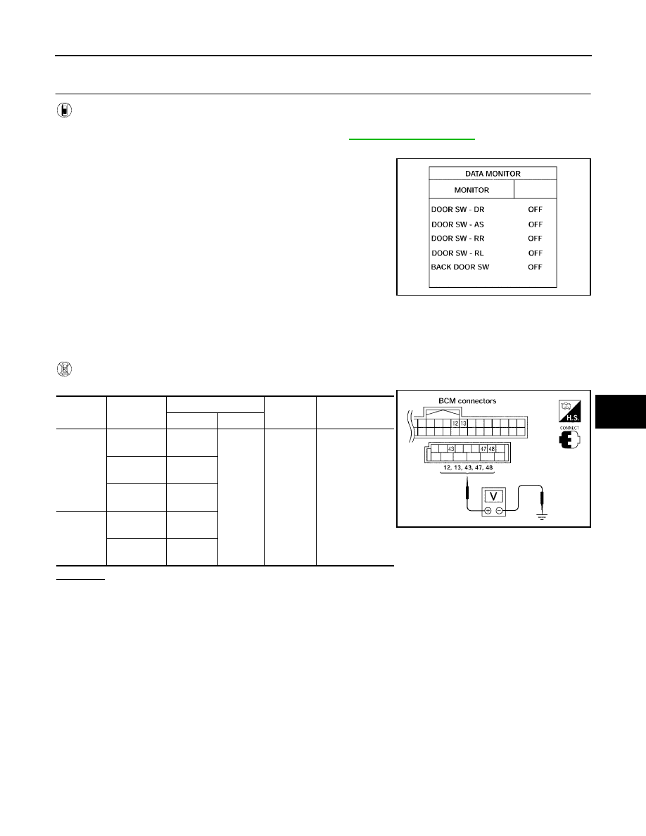
Door Switch Check
EIS007ON
1.
CHECK DOOR SWITCHES INPUT SIGNAL
With CONSULT-II
Check door switches ("DOOR SW-DR", "DOOR SW-AS", "DOOR SW-RL", "DOOR SW-RR", "BACK DOOR
SW") in DATA MONITOR mode with CONSULT–II. Refer to
.
●
When doors are open:
●
When doors are closed:
Without CONSULT-II
Check voltage between BCM connector M18 or M19 terminals 12, 13, 42, 43, 47, 48 and ground.
OK or NG
OK
>> Door switch circuit is OK.
NG
>> GO TO 2.
DOOR SW-DR
: ON
DOOR SW-AS
: ON
DOOR SW-RL
: ON
DOOR SW-RR
: ON
BACK DOOR SW
: ON
DOOR SW-DR
: OFF
DOOR SW-AS
: OFF
DOOR SW-RL
: OFF
DOOR SW-RR
: OFF
BACK DOOR SW
: OFF
LIIA0665E
Connec-
tor
Item
Terminals
Condition
Voltage (V)
(Approx.)
(+)
(–)
M19
Back door
switch
43
Ground
Open
↓
Closed
0
↓
Battery voltage
Front door
switch LH
47
Rear door
switch LH
48
M18
Front door
switch RH
12
Rear door
switch RH
13
LIIA1041E