Nissan Pathfinder (2006 year). Manual - part 30


  Index      Manuals     Nissan Pathfinder (2006 year) - Service and Repair Manual


Search            copyright infringement  


Content      ..     28      29      30      31     ..


Nissan Pathfinder (2006 year). Manual - part 30


ON-VEHICLE SERVICE

AT-231

D

E

F

G

H

I

J

K

L

M

A

B

AT

2006 Pathfinder

ON-VEHICLE SERVICE

PFP:00000

Oil Pan

ECS00ELT

REMOVAL AND INSTALLATION
Removal

1.

Drain A/T fluid. Refer to 

MA-24, "Changing the Automatic Transmission Fluid (ATF)"

 .

2.

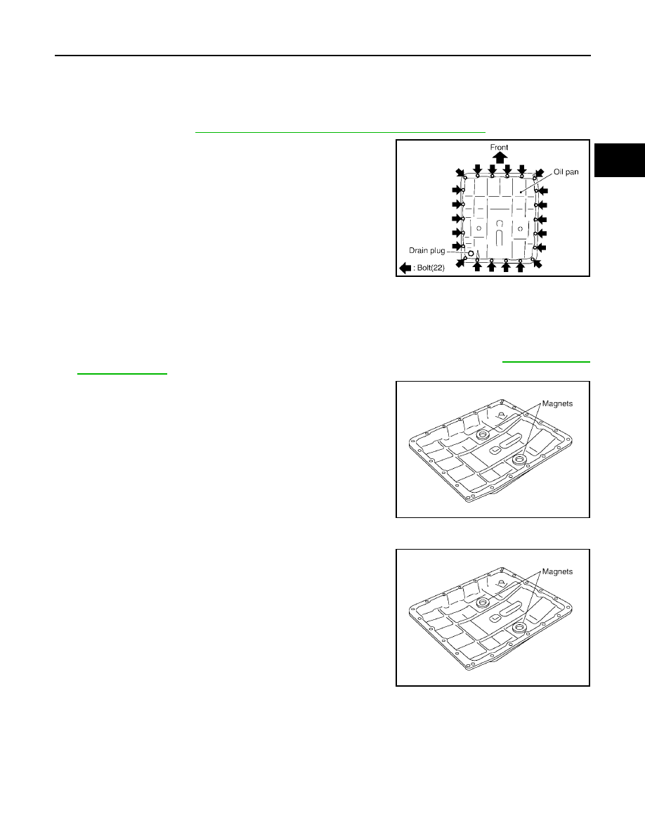
Remove oil pan and gasket.

3.

Check for foreign materials in oil pan to help determine cause of malfunction. If the A/T fluid is very dark,
has some burned smell, or contains foreign particles then friction material (clutches, band) may need
replacement. A tacky film that will not wipe clean indicates varnish build up. Varnish can cause valves,
servo, and clutches to stick and can inhibit pump pressure.

CAUTION:

If friction material is detected, flush the transmission cooler after repair. Refer to 

AT-15, "A/T Fluid

Cooler Cleaning"

 .

4.

Remove magnets from oil pan.

Installation

1.

Install the oil pan magnets as shown.

SCIA2308E

SCIA5200E

SCIA5200E

AT-232

ON-VEHICLE SERVICE

2006 Pathfinder

2.

Install the oil pan and new oil pan gasket.

CAUTION:

Be sure the oil drain plug is located to the rear of the
transmission assembly.

Before installing oil pan bolts, remove any traces of old
sealant from the sealing surfaces and threaded holes.

Do not reuse old gasket, replace with a new one.

Always replace the oil pan bolts as they are self-sealing.

Partially install the oil pan bolts in a criss-cross pattern to
prevent dislocation of the gasket.

3.

Tighten oil pan bolts in numerical order as shown.

4.

Install drain plug to oil pan and tighten to specification.

CAUTION:

Do not reuse old drain plug gasket replace with a new one.

5.

Refill the A/T with fluid and check for fluid leakage. Refer to 

MA-24, "Changing the Automatic Transmis-

sion Fluid (ATF)"

 .

SCIA2308E

Oil pan bolts

: 7.9 N·m (0.81 kg-m, 70 in-lb)

SCIA4113E

Drain plug

: 34 N·m (3.5 kg-m, 25 ft-lb)

ON-VEHICLE SERVICE

AT-233

D

E

F

G

H

I

J

K

L

M

A

B

AT

2006 Pathfinder

Control Valve With TCM and A/T Fluid Temperature Sensor 2

ECS00ELU

COMPONENTS

1.

Transmission

2.

Snap ring

3.

Sub-harness

4.

Control valve with TCM

5.

Bracket

6.

A/T fluid temperature sensor 2

7.

Oil pan gasket

8.

Oil pan

9.

Magnet

10. Drain plug

11.

Drain plug gasket

12. Oil pan bolt

13. Terminal cord assembly

14. O-ring

SCIA5478E

AT-234

ON-VEHICLE SERVICE

2006 Pathfinder

CONTROL VALVE WITH TCM REMOVAL AND INSTALLATION
Removal

1.

Disconnect negative battery terminal.

2.

Drain A/T fluid. Refer to 

MA-24, "Changing the Automatic Transmission Fluid (ATF)"

 .

3.

Disconnect A/T assembly harness connector.

4.

Remove snap ring from A/T assembly harness connector.

5.

Push A/T assembly harness connector.

CAUTION:

Be careful not to damage connector.

6.

Remove oil pan and oil pan gasket. Refer to 

AT-231, "Removal"

 .

7.

Straighten the terminal clip to free the terminal cord assembly for
A/T fluid temperature sensor 2 harness.

8.

Disconnect A/T fluid temperature sensor 2 connector.

CAUTION:

Be careful not to damage connector.

9.

Straighten terminal clips to free revolution sensor harness.

10. Disconnect revolution sensor connector.

CAUTION:

Be careful not to damage connector.

SCIA5021E

SCIA5022E

SCIA5446E

SCIA7022E

ON-VEHICLE SERVICE

AT-235

D

E

F

G

H

I

J

K

L

M

A

B

AT

2006 Pathfinder

11. Remove bolts A, B and C from control valve with TCM.

12. Remove control valve with TCM from transmission case.

CAUTION:

When removing, be careful with the manual valve notch and
manual plate height. Remove it vertically.

13. Remove A/T fluid temperature sensor 2 with bracket from con-

trol valve with TCM.

14. Remove bracket from A/T fluid temperature sensor 2.

15. Remove O-ring from A/T assembly harness connector.

Bolt symbol

Length mm (in)

Number of bolts

A

42 (1.65)

5

B

55 (2.17)

6

C

40 (1.57)

1

SCIA5139E

SCIA5142E

SCIA5301E

SCIA5264E

SCIA5155E

AT-236

ON-VEHICLE SERVICE

2006 Pathfinder

16. Disconnect TCM connectors.

CAUTION:

Be careful not to damage connectors.

17. Remove A/T assembly harness connector from control valve

with TCM using suitable tool.

18. Disconnect TCM connector and park/neutral position switch

connector

CAUTION:

Be careful not to damage connectors.

SCIA5447E

SCIA5448E

SCIA5449E

ON-VEHICLE SERVICE

AT-237

D

E

F

G

H

I

J

K

L

M

A

B

AT

2006 Pathfinder

Installation

1.

Connect TCM connector and park/neutral position switch con-
nector.

2.

Install A/T assembly harness connector to control valve with
TCM.

3.

Connect TCM connector.

4.

Install new O-ring in A/T assembly harness connector.

CAUTION:

Do not reuse O-ring.

Apply ATF to O-ring.

SCIA5449E

SCIA5450E

SCIA5447E

SCIA5155E

AT-238

ON-VEHICLE SERVICE

2006 Pathfinder

5.

Install A/T fluid temperature sensor 2 to bracket.

6.

Install A/T fluid temperature sensor 2 (with bracket) in control
valve with TCM. Tighten A/T fluid temperature sensor 2 bolt to
the specified torque. Refer to 

AT-233, "COMPONENTS"

 .

CAUTION:

Adjust bolt hole of bracket to bolt hole of control valve with
TCM.

7.

Install control valve with TCM in transmission case.

CAUTION:

Make sure that turbine revolution sensor is securely
installed into turbine revolution sensor hole.

Hang down revolution sensor harness toward outside so
as not to disturb installation of control valve with TCM.

Adjust A/T assembly harness connector of control valve
with TCM to terminal hole of transmission case.

Assemble it so that manual valve cutout is engaged with
manual plate projection.

SCIA5264E

SCIA5301E

SCIA5034E

SCIA5142E


Content      ..     28      29      30      31     ..