Nissan Pathfinder (2006 year). Manual - part 29


  Index      Manuals     Nissan Pathfinder (2006 year) - Service and Repair Manual


Search            copyright infringement  


Content      ..     27      28      29      30     ..


Nissan Pathfinder (2006 year). Manual - part 29


A/T SHIFT LOCK SYSTEM

AT-223

D

E

F

G

H

I

J

K

L

M

A

B

AT

2006 Pathfinder

A/T SHIFT LOCK SYSTEM

PFP:34950

Description

ECS00ELN

The mechanical key interlock mechanism also operates as a shift lock:
With the ignition switch turned to ON, the selector lever cannot be shifted from “P” (parking) to any other
position unless the brake pedal is depressed.
With the key removed, the selector lever cannot be shifted from “P” to any other position.
The key cannot be removed unless the selector lever is placed in “P” position.

The shift lock and key interlock mechanisms are controlled by the ON-OFF operation of the shift lock sole-
noid and by the operation of the rotator and slider located inside the key cylinder, respectively.

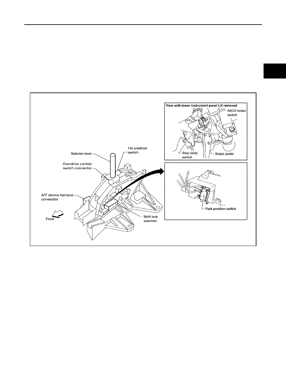
Shift Lock System Electrical Parts Location

ECS00ELO

WCIA0528E

AT-224

A/T SHIFT LOCK SYSTEM

2006 Pathfinder

Wiring Diagram — A/T — SHIFT

ECS00ELP

BCWA0570E

A/T SHIFT LOCK SYSTEM

AT-225

D

E

F

G

H

I

J

K

L

M

A

B

AT

2006 Pathfinder

Diagnostic Procedure

ECS00ELQ

SYMPTOM 1:

Selector lever cannot be moved from “P” position with key in ON position and brake pedal
applied.

Selector lever can be moved from “P” position with key in ON position and brake pedal released.

Selector lever can be moved from “P” position when key is removed from key cylinder.

SYMPTOM 2:

Ignition key cannot be removed when selector lever is set to “P” position.

Ignition key can be removed when selector lever is set to any position except “P”.

1. 

CHECK KEY INTERLOCK CABLE

Check key interlock cable for damage.

OK or NG

OK

>> GO TO 2.

NG

>> Repair key interlock cable. Refer to 

AT-228, "KEY INTERLOCK CABLE"

 .

2. 

CHECK SELECTOR LEVER POSITION

Check selector lever position for damage. Refer to 

AT-222, "Checking of A/T Position"

 .

OK or NG

OK

>> GO TO 3.

NG

>> Check selector lever. Refer to 

AT-222, "Adjustment of A/T Position"

 .

3. 

CHECK INPUT SIGNAL A/T DEVICE

1.

Turn ignition switch “OFF”.

2.

Disconnect A/T device harness connector.

3.

Check voltage between A/T device harness connector M156 ter-
minal 1 and ground.

OK or NG

OK

>> GO TO 5.

NG

>> GO TO 4.

Voltage

Depressed brake pedal

:Battery voltage

Released brake pedal

:Approx. 0V

SCIA6265E

AT-226

A/T SHIFT LOCK SYSTEM

2006 Pathfinder

4. 

DETECT MALFUNCTIONING ITEM

Check the following.

1.

Harness for short or open between ignition switch and stop lamp switch harness connector E38 terminal
3.

2.

Harness for short or open between stop lamp switch harness connector E38 terminal 4 and A/T device
harness connector M156 terminal 1.

3.

10A fuse. [No.12, located in the fuse block (J/B)]

4.

Stop lamp switch.

Check continuity between stop lamp switch terminals 3 and 4.

Check stop lamp switch after adjusting brake pedal — refer to   

BR-6, "BRAKE PEDAL"

 .

OK or NG

OK

>> GO TO 5.

NG

>> Repair or replace damaged parts.

5. 

CHECK GROUND CIRCUIT

1.

Turn ignition switch “OFF”.

2.

Disconnect A/T device harness connector.

3.

Check continuity between A/T device harness connector M156
terminal 2 and ground.

If OK, check harness for short to ground and short to power.

OK or NG

OK

>> GO TO 6.

NG

>> Repair open circuit or short to ground or short to power

in harness or connectors.

SCIA3953E

Continuity should exist.

SCIA6266E

A/T SHIFT LOCK SYSTEM

AT-227

D

E

F

G

H

I

J

K

L

M

A

B

AT

2006 Pathfinder

6. 

CHECK PARK POSITION SWITCH AND SHIFT LOCK SOLENOID CIRCUIT

Check continuity between A/T device terminals 1 and 2.

OK or NG

OK

>> INSPECTION END

NG

>>

Replace park position switch or shift lock solenoid.

Repair open circuit or short to ground or short to power in harness or connectors.

SCIA6267E

AT-228

KEY INTERLOCK CABLE

2006 Pathfinder

KEY INTERLOCK CABLE

PFP:34908

Components

ECS00ELR

CAUTION:

Install key interlock cable in such a way that it will not be damaged by sharp bends, twists or inter-
ference with adjacent parts.

After installing key interlock cable to control device, make sure that casing cap and bracket are
firmly secured in their positions. If casing cap can be removed with an external load of less than
39 N (4.0 kg, 8.8 lb), replace key interlock cable with new one.

WCIA0467E

KEY INTERLOCK CABLE

AT-229

D

E

F

G

H

I

J

K

L

M

A

B

AT

2006 Pathfinder

Removal and Installation

ECS00ELS

REMOVAL

1.

Unlock slider by squeezing lock tabs on slider from adjuster
holder.

2.

Remove casing cap from bracket of control device assembly
and remove interlock rod from adjuster holder.

3.

Remove holder from key cylinder and remove key interlock
cable.

SCIA1230E

LCIA0375E

AT-230

KEY INTERLOCK CABLE

2006 Pathfinder

INSTALLATION

1.

Set key interlock cable to key cylinder and install holder.

2.

Turn ignition key to lock position.

3.

Set selector lever to “P” position.

4.

Insert interlock rod into adjuster holder.

5.

Install casing cap to bracket.

6.

Move slider in order to secure adjuster holder to interlock rod.

SCIA2258E

SCIA1232E


Content      ..     27      28      29      30     ..