Nissan Pathfinder (2006 year). Manual - part 23


  Index      Manuals     Nissan Pathfinder (2006 year) - Service and Repair Manual


Search            copyright infringement  


Content      ..     21      22      23      24     ..


Nissan Pathfinder (2006 year). Manual - part 23


MAIN POWER SUPPLY AND GROUND CIRCUIT

AT-175

D

E

F

G

H

I

J

K

L

M

A

B

AT

2006 Pathfinder

3. 

DETECT MALFUNCTIONING ITEM

Check the following.

Harness for short or open between battery and A/T assembly harness connector terminals 1, 2

Harness for short or open between ignition switch and A/T assembly harness connector terminal 6

10A fuse (No. 22, located in the fuse and fusible link block) and 10A fuse (No. 49, located in the IPDM E/
R)

Ignition switch. Refer to 

PG-4, "POWER SUPPLY ROUTING CIRCUIT"

 .

OK or NG

OK

>> GO TO 4.

NG

>> Repair or replace damaged parts.

4. 

CHECK TCM GROUND CIRCUIT

1.

Turn ignition switch OFF.

2.

Disconnect A/T assembly harness connector.
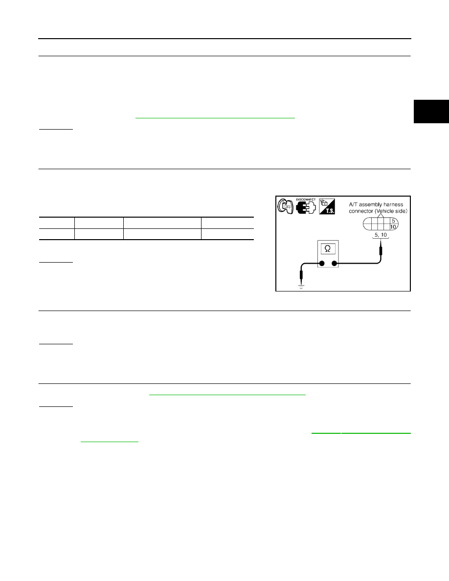
3.

Check continuity between A/T assembly harness connector ter-
minals and ground.

If OK, check harness for short to ground and short to power.

OK or NG

OK

>> GO TO 5.

NG

>> Repair open circuit or short to ground or short to power

in harness or connectors.

5. 

DETECT MALFUNCTIONING ITEM

Check the following.

The A/T assembly harness connector terminals for damage or loose connection with harness connector.

OK or NG

OK

>> GO TO 6.

NG

>> Repair or replace damaged parts.

6. 

PERFORM SELF-DIAGNOSIS

Perform self-diagnosis. Refer to 

AT-90, "SELF-DIAGNOSTIC RESULT MODE"

 .

OK or NG

OK

>> INSPECTION END

NG-1

>> Self-diagnosis does not activate: GO TO 7.

NG-2

>> DTC is displayed: Check the malfunctioning system. Refer to 

AT-90, "SELF-DIAGNOSTIC

RESULT MODE"

 .

Item

Connector

Terminal

Continuity

TCM

F9

5, 10 - Ground

Yes

SCIA2106E

AT-176

MAIN POWER SUPPLY AND GROUND CIRCUIT

2006 Pathfinder

7. 

CHECK TERMINAL CORD ASSEMBLY

1.

Remove control valve with TCM. Refer to 

AT-233, "Control Valve With TCM and A/T Fluid Temperature

Sensor 2"

 .

2.

Disconnect A/T assembly harness connector and TCM connector.

3.

Check continuity between A/T assembly harness connector ter-
minals and TCM connector terminals.

4.

Check continuity between A/T assembly harness connector ter-
minals and TCM connector terminals.

5.

If OK, check harness for short to ground and short to power.

OK or NG

OK

>> Replace the control valve with TCM. Refer to 

AT-233, "Control Valve With TCM and A/T Fluid

Temperature Sensor 2"

 .

NG

>> Replace open circuit or short to ground and short to power in harness or connectors.

Item

Connector

Terminal

Voltage

A/T assembly harness connector

F9

1

Yes

TCM connector 

F502

9

A/T assembly harness connector

F9

2

Yes

TCM connector 

F502

10

A/T assembly harness connector

F9

6

Yes

TCM connector 

F502

4

SCIA5464E

Item

Connector

Terminal

Voltage

A/T assembly harness connector

F9

5

Yes

TCM connector 

F504

21

A/T assembly harness connector

F9

10

Yes

TCM connector 

F504

22

SCIA5465E

CLOSED THROTTLE POSITION AND WIDE OPEN THROTTLE POSITION CIR-

CUIT

AT-177

D

E

F

G

H

I

J

K

L

M

A

B

AT

2006 Pathfinder

CLOSED THROTTLE POSITION AND WIDE OPEN THROTTLE POSITION CIR-
CUIT

PFP:18002

CONSULT-II Reference Value

ECS00EKS

Diagnostic Procedure

ECS00EKT

1. 

CHECK CAN COMMUNICATION LINE

Perform the self-diagnosis. Refer to 

AT-90, "SELF-DIAGNOSTIC RESULT MODE"

 .

Is a malfunction in the CAN communication indicated in the results?

YES

>> Check CAN communication line. Refer to 

AT-103, "DTC U1000 CAN COMMUNICATION LINE"

 .

NO

>> GO TO 2.

2. 

CHECK THROTTLE POSITION SIGNAL CIRCUIT

 With CONSULT-II

1.

Turn ignition switch “ON”. (Do not start engine.)

2.

Select “ECU INPUT SIGNALS” in “DATA MONITOR” mode for
“A/T” with CONSULT-II.

3.

Depress accelerator pedal and read out the value of “CLSD THL
POS” and “W/O THL POS”.

OK or NG

OK

>> INSPECTION END

NG

>> Check the following. If NG, repair or replace damaged 

parts.

Perform the self-diagnosis for “ENGINE” with CON-
SULT-II.

Open circuit or short to ground or short to power in harness or connectors.

Pin terminals for damage or loose connection with harness connector.

Item name

Condition 

Display value

CLSD THL POS

Released accelerator pedal.

ON

Fully depressed accelerator pedal.

OFF

W/O THL POS

Fully depressed accelerator pedal.

ON

Released accelerator pedal.

OFF

PCIA0070E

AT-178

BRAKE SIGNAL CIRCUIT

2006 Pathfinder

BRAKE SIGNAL CIRCUIT

PFP:25320

CONSULT-II Reference Value

ECS00EKU

Diagnostic Procedure

ECS00EKV

1. 

CHECK CAN COMMUNICATION LINE

Perform the self-diagnosis. Refer to 

AT-90, "SELF-DIAGNOSTIC RESULT MODE"

 .

Is a malfunction in the CAN communication indicated in the results?

YES

>> Check CAN communication line. Refer to 

AT-103, "DTC U1000 CAN COMMUNICATION LINE"

 .

NO

>> GO TO 2.

2. 

CHECK STOP LAMP SWITCH CIRCUIT

 With CONSULT-II

1.

Turn ignition switch “ON”. (Do not start engine.)

2.

Select “ECU INPUT SIGNALS” in “DATA MONITOR” mode for
“A/T” with CONSULT-II.

3.

Read out ON/OFF switching action of the “BRAKE SW”.

OK or NG

OK

>> INSPECTION END

NG

>> GO TO 3.

3. 

CHECK STOP LAMP SWITCH

Check continuity between stop lamp switch harness connector termi-
nals 1 and 2.

Check stop lamp switch after adjusting brake pedal — refer to

BR-6, "BRAKE PEDAL"

 .

OK or NG

OK

>> Check the following. If NG, repair or replace damaged parts.

Harness for short or open between battery and stop lamp switch.

Harness for short or open between stop lamp switch and combination meter.

NG

>> Repair or replace the stop lamp switch.

Item name

Condition

Display value

BRAKE SW

Depressed brake pedal.

ON

Released brake pedal.

OFF

PCIA0070E

Item

Condition

Terminal

Continuity

Stop lamp 

switch har-

ness connec-

tor

When brake pedal is 
depressed

1 - 2

Yes

When brake pedal is released

No

SCIA2144E

OVERDRIVE CONTROL SWITCH

AT-179

D

E

F

G

H

I

J

K

L

M

A

B

AT

2006 Pathfinder

OVERDRIVE CONTROL SWITCH

PFP:25130

CONSULT-II Reference Value

ECS00EKW

Diagnostic Procedure

ECS00EKX

1. 

CHECK CAN COMMUNICATION LINE

Perform the self-diagnosis. Refer to 

AT-90, "SELF-DIAGNOSTIC RESULT MODE"

 .

Is any malfunction in the CAN communication indicated in the results?

YES

>> Check CAN communication line. Refer to 

AT-103, "DTC U1000 CAN COMMUNICATION LINE"

 .

NO

>> GO TO 2.

2. 

CHECK OVERDRIVE CONTOROL SWITCH CIRCUIT

 With CONSULT-II

1.

Turn ignition switch “ON”.

2.

Select “ECU INPUT SIGNALS” in “DATA MONITOR” mode for
“A/T” with CONSULT-II.

3.

Read out “OD CONT SW”.
Check the signal of the overdrive control switch is indicated
properly.

 Without CONSULT-II

1.

Turn ignition switch “ON”. (Do not start engine)

2.

Check voltage between A/T control device connector terminal and ground.

OK or NG

OK

>> GO TO 5.

NG

>> GO TO 3.

Item name

Condition

Display value

OD CONT SW

Releasing overdrive control switch

OFF

Holding overdrive control switch

ON

Monitor item

Condition

Display value

OD CONT SW

Releasing overdrive control switch

OFF

Holding overdrive control switch

ON

LCIA0339E

Item

Connector 

No.

Terminal No.

Condition

Data

(Approx.)

Overdrive 

control switch

M156

7 - Ground

Releasing overdrive 
control switch

Battery 
voltage 

Holding overdrive 
control switch

0V

AT-180

OVERDRIVE CONTROL SWITCH

2006 Pathfinder

3. 

CHECK OVERDRIVE CONTROL SWITCH

1.

Turn ignition switch “OFF”.

2.

Disconnect A/T control device connector.

3.

Check continuity between A/T control device connector M156 terminals 7 and 8.

OK or NG

OK

>> GO TO 4.

NG

>> Repair or replace overdrive control switch.

4. 

DETECT MALFUNCTIONING ITEM

Check the following. If any items are damaged, repair or replace damaged parts.

Harness for short or open between combination meter connector terminal 20 and A/T control device con-
nector terminal 7.

Harness for short or open between A/T control device connector terminal 8 and ground.

OK or NG

OK

>> GO TO 5.

NG

>> Repair or replace damaged parts.

5. 

CHECK COMBINATION METER

Check the combination meter. Refer to 

DI-19, "How to Proceed With Trouble Diagnosis"

 .

OK or NG

OK

>> INSPECTION END

NO

>> Repair or replace damaged parts.

Condition

Continuity

Releasing overdrive control switch

No

Holding overdrive control switch

Yes

TROUBLE DIAGNOSIS FOR SYMPTOMS

AT-181

D

E

F

G

H

I

J

K

L

M

A

B

AT

2006 Pathfinder

TROUBLE DIAGNOSIS FOR SYMPTOMS

PFP:00007

Wiring Diagram — AT — NONDTC

ECS00EKY

BCWA0569E

AT-182

TROUBLE DIAGNOSIS FOR SYMPTOMS

2006 Pathfinder

BCWA0577E


Content      ..     21      22      23      24     ..