Nissan Pathfinder (2006 year). Manual - part 22
DTC P1843 ATF PRESSURE SWITCH 3
AT-167
D
E
F
G
H
I
J
K
L
M
A
B
AT
2006 Pathfinder
DTC P1843 ATF PRESSURE SWITCH 3
PFP:25240
Description
ECS00EK8
Fail-safe function to detect input clutch solenoid valve condition.
CONSULT-II Reference Value
ECS00EK9
On Board Diagnosis Logic
ECS00EKA
●
This is not an OBD-II self-diagnostic item.
●
Diagnostic trouble code “P1843 ATF PRES SW 3/CIRC” with CONSULT-II is detected when TCM detects
that actual gear ratio is normal, and relation between gear position and condition of ATF pressure switch 3
is irregular during depressing accelerator pedal. (Other than during shift change)
Possible Cause
ECS00EKB
●
ATF pressure switch 3
●
Harness or connectors
(The switch circuit is open or shorted.)
DTC Confirmation Procedure
ECS00EKC
CAUTION:
Always drive vehicle at a safe speed.
NOTE:
If “DTC Confirmation Procedure” has been previously performed, always turn ignition switch “OFF”
and wait at least 10 seconds before performing the next test.
After the repair, perform the following procedure to confirm the malfunction is eliminated.
WITH CONSULT-II
1.
Start engine.
2.
Accelerate vehicle to maintain the following conditions.
ACCELE POS: 1.5/8 - 2.0/8
Selector lever: “D” position
Gear position: 3rd
Þ
4th Gear (I/C ON/OFF)
Driving location: Driving the vehicle uphill (increased
engine load) will help maintain the driving conditions
required for this test.
3.
Perform step “2” again.
4.
Turn ignition switch “OFF”, then perform step “1” to “3” again.
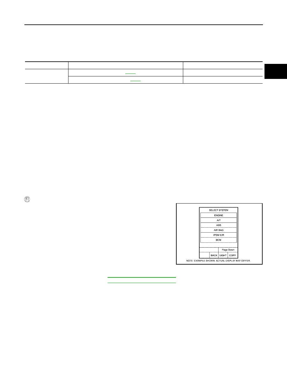
5.
Check “SELF-DIAG RESULTS” mode for “A/T” with CONSULT-
II.
If DTC (P1843) is detected, go to
AT-168, "Diagnostic Procedure"
.
If DTC (P1752) is detected, go to
AT-146, "Diagnostic Procedure"
.
Item name
Condition
Display value
ATF PRES SW 3
Input clutch engaged. Refer to
.
ON
Input clutch disengaged. Refer to
.
OFF
BCIA0030E