Nissan Pathfinder (2006 year). Manual - part 12


  Index      Manuals     Nissan Pathfinder (2006 year) - Service and Repair Manual


Search            copyright infringement  


Content      ..     10      11      12      13     ..


Nissan Pathfinder (2006 year). Manual - part 12


TROUBLE DIAGNOSIS

AT-87

D

E

F

G

H

I

J

K

L

M

A

B

AT

2006 Pathfinder

CONSULT-II Function (A/T)

ECS00EFG

FUNCTION

CONSULT-II REFERENCE VALUE

NOTICE:
1.

The CONSULT-II electrically displays shift timing and lock-up timing (that is, operation timing of each sole-
noid).
Check for time difference between actual shift timing and the CONSULT-II display. If the difference is
noticeable, mechanical parts (except solenoids, sensors, etc.) may be malfunctioning. Check mechanical
parts using applicable diagnostic procedures.

2.

Shift schedule (which implies gear position) displayed on CONSULT-II and that indicated in Service Man-
ual may differ slightly. This occurs because of the following reasons:

Actual shift schedule has more or less tolerance or allowance,

Shift schedule indicated in Service Manual refers to the point where shifts start, and

Gear position displayed on CONSULT-II indicates the point where shifts are completed.

3.

Display of solenoid valves on CONSULT-II changes at the start of shifting, while gear position is displayed
upon completion of shifting (which is computed by TCM).

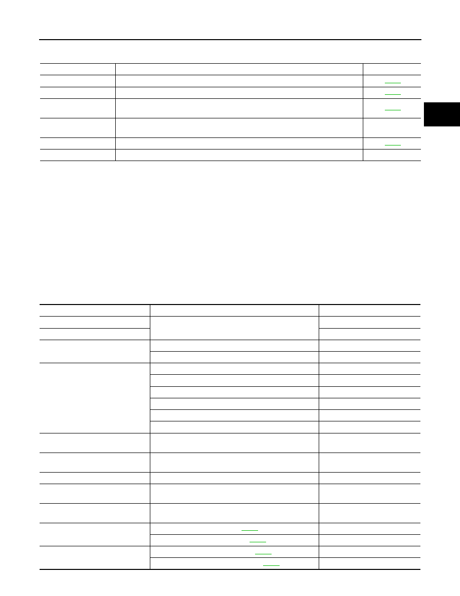
Diagnostic test mode

Function

Reference page

Self-diagnostic results

Self-diagnostic results can be read and erased quickly.

AT-90

Data monitor

Input/Output data in the TCM can be read.

AT-93

CAN diagnostic support 
monitor

The results of transmit/receive diagnosis of CAN communication can be read.

AT-98

Function test

Conducted by CONSULT-II instead of a technician to determine whether each system 
is “OK” or “NG”.

DTC work support

Select the operating condition to confirm Diagnosis Trouble Codes.

AT-98

ECU part number

TCM part number can be read.

Item name

Condition 

Display value (Approx.)

ATF TEMP SE 1

0

°

C (32

°

 F) - 20

°

C (68

°

F) - 80

°

C (176

°

F)

3.3 - 2.7 - 0.9 V

ATF TEMP SE 2

3.3 - 2.5 - 0.7 V

TCC SOLENOID

When perform slip lock-up

0.2 - 0.4 A

When perform lock-up

0.4 - 0.6 A

SLCT LVR POSI

Selector lever in “N”,“P” positions.

N/P

Selector lever in “R” position.

R

Selector lever in “D” position.

D

Selector lever in “3” position.

3

Selector lever in “2” position.

2

Selector lever in “1” position.

1

VHCL/S SE·A/T

During driving

Approximately matches the 
speedometer reading.

ENGINE SPEED

Engine running

Closely matches the tachometer 
reading.

LINE PRES SOL

During driving

0.2 - 0.6 A

TURBINE REV

During driving (lock-up ON)

Approximately matches the 
engine speed.

VHCL/S SE·MTR

During driving

Approximately matches the 
speedometer reading.

ATF PRES SW 1

Front brake engaged. Refer to 

AT-22

ON

Front brake disengaged. Refer to 

AT-22

OFF

ATF PRES SW 2

Low coast brake engaged. Refer to 

AT-22

ON

Low coast brake disengaged. Refer to 

AT-22

OFF

AT-88

TROUBLE DIAGNOSIS

2006 Pathfinder

ATF PRES SW 3

Input clutch engaged. Refer to 

AT-22

ON

Input clutch disengaged. Refer to 

AT-22

OFF

ATF PRES SW 5

Direct clutch engaged. Refer to 

AT-22

ON

Direct clutch disengaged. Refer to 

AT-22

OFF

ATF PRES SW 6

High and low reverse clutch engaged. Refer to 

AT-22

ON

High and low reverse clutch disengaged. Refer to 

AT-22

OFF

I/C SOLENOID

Input clutch disengaged. Refer to 

AT-22

0.6 - 0.8 A

Input clutch engaged. Refer to 

AT-22

0 - 0.05 A

FR/B SOLENOID

Front brake engaged. Refer to 

AT-22

0.6 - 0.8 A

Front brake disengaged. Refer to 

AT-22

0 - 0.05 A

D/C SOLENOID

Direct clutch disengaged. Refer to 

AT-22

0.6 - 0.8 A

Direct clutch engaged. Refer to 

AT-22

0 - 0.05 A

HLR/C SOL

High and low reverse clutch disengaged. Refer to 

AT-22

0.6 - 0.8 A

High and low reverse clutch engaged. Refer to 

AT-22

0 - 0.05 A

ON OFF SOL

Low coast brake engaged. Refer to 

AT-22

ON

Low coast brake disengaged. Refer to 

AT-22

OFF

STARTER RELAY

Selector lever in “N”,“P” positions.

ON

Selector lever in other position.

OFF

ACCELE POSI

Released accelerator pedal.

0.0/8

Fully depressed accelerator pedal.

8/8

CLSD THL POS

Released accelerator pedal.

ON

Fully depressed accelerator pedal.

OFF

W/O THL POS

Fully depressed accelerator pedal.

ON

Released accelerator pedal.

OFF

OD CONT SW

Releasing overdrive control switch

OFF

Holding overdrive control switch

ON

BRAKE SW

Depressed brake pedal.

ON

Released brake pedal.

OFF

Item name

Condition 

Display value (Approx.)

TROUBLE DIAGNOSIS

AT-89

D

E

F

G

H

I

J

K

L

M

A

B

AT

2006 Pathfinder

CONSULT-II SETTING PROCEDURE

CAUTION:

If CONSULT-II is used with no connection of CONSULT-II CONVERTER, malfunctions might be
detected in self-diagnosis depending on control unit which carry out CAN communication.

For details, refer to the separate “CONSULT-II Operations Man-
ual”.

1.

Turn ignition switch “OFF”.

2.

Connect CONSULT-II and CONSULT-II CONVERTER to data
link connector, which is located in instrument lower panel on
driver side.

3.

Turn ignition switch “ON”. (Do not start engine.)

4.

Touch “START (NISSAN BASED VHCL)”. 

5.

Touch “A/T”.
If “A/T” is not indicated, go to 

GI-40, "CONSULT-II Data Link

Connector (DLC) Circuit"

 .

6.

Perform each diagnostic test mode according to each service
procedure.

BBIA0369E

BCIA0029E

BCIA0030E

AT-90

TROUBLE DIAGNOSIS

2006 Pathfinder

SELF-DIAGNOSTIC RESULT MODE
Operation Procedure

After performing 

AT-90, "SELF-DIAGNOSTIC RESULT MODE"

 , place check marks for results on th

AT-48,

"DIAGNOSTIC WORKSHEET"

 . Reference pages are provided following the items.

1.

Perfor

AT-89, "CONSULT-II SETTING PROCEDURE"

 .

2.

Touch “SELF-DIAG RESULTS”.
Display shows malfunction experienced since the last erasing
operation.

Display Items List

X: Applicable, —: Not applicable

BCIA0031E

 Items (CONSULT-II 

screen terms)

Malfunction is detected when...

TCM self-

diagnosis

OBD-II (DTC)

Reference 

page

 “A/T” with   

CONSULT-II

MIL indicator 

lamp*1, 

“ENGINE” with 

CONSULT-II or 

GST

CAN COMM CIRCUIT

When a malfunction is detected in CAN communica-
tions

U1000

U1000

AT-103

STARTER RELAY/
CIRC

If this signal is ON other than in “P” or “N” position, 
this is judged to be a malfunction.
(And if it is OFF in “P” or “N” position, this too is 
judged to be a malfunction.)

P0615

AT-106

TCM

TCM is malfunctioning.

P0700

P0700

AT-110

PNP SW/CIRC

PNP switch 1-4 signals input with impossible pattern

“P” position is detected from “N” position without any 
other position being detected in between.

P0705

P0705

AT-111

TURBINE REV S/CIRC

TCM does not receive the proper voltage signal from 
the sensor.

TCM detects an irregularity only at position of 4th 
gear for turbine revolution sensor 2.

P0717

P0717

AT-115

VEH SPD SEN/CIR AT 
(Revolution sensor)

Signal from vehicle speed sensor A/T (Revolution 
sensor) not input due to cut line or the like

Unexpected signal input during running

After ignition switch is turned ON, unexpected signal 
input from vehicle speed sensor MTR before the 
vehicle starts moving

P0720

P0720

AT-117

ENGINE SPEED SIG

TCM does not receive the CAN communication sig-
nal from the ECM.

P0725

AT-122

TCC SOLENOID/CIRC

Normal voltage not applied to solenoid due to cut 
line, short, or the like

P0740

P0740

AT-124

A/T TCC S/V FNCTN

A/T cannot perform lock-up even if electrical circuit 
is good.

TCM detects as irregular by comparing difference 
value with slip rotation.

P0744

P0744*2

AT-126

TROUBLE DIAGNOSIS

AT-91

D

E

F

G

H

I

J

K

L

M

A

B

AT

2006 Pathfinder

L/PRESS SOL/CIRC

Normal voltage not applied to solenoid due to cut 
line, short, or the like

TCM detects as irregular by comparing target value 
with monitor value.

P0745

P0745

AT-128

TP SEN/CIRC A/T

TCM does not receive the proper accelerator pedal 
position signals (input by CAN communication) from 
ECM.

P1705

AT-130

ATF TEMP SEN/CIRC

 During running, the ATF temperature sensor signal 
voltage is excessively high or low

P1710

P0710

AT-133

VEH SPD SE/CIR·MTR

Signal (CAN communication) from vehicle speed 
sensor MTR not input due to cut line or the like

Unexpected signal input during running

P1721

AT-138

A/T INTERLOCK

Except during shift change, the gear position and 
ATF pressure switch states are monitored and com-
parative judgement made.

P1730

P1730

AT-140

A/T 1ST E/BRAKING

Each ATF pressure switch and solenoid current is 
monitored and if a pattern is detected having engine 
braking 1st gear other than in the “1” position, a mal-
function is detected.

P1731

AT-143

I/C SOLENOID/CIRC

Normal voltage not applied to solenoid due to func-
tional malfunction, cut line, short, or the like

TCM detects as irregular by comparing target value 
with monitor value.

P1752

P1752

AT-145

I/C SOLENOID FNCTN 

TCM detects that actual gear ratio is irregular, and 
relation between gear position and condition of ATF 
pressure switch 3 is irregular during depressing 
accelerator pedal. (Other than during shift change)

TCM detects that relation between gear position and 
condition of ATF pressure switch 3 is irregular during 
releasing accelerator pedal. (Other than during shift 
change)

P1754

P1754*2

AT-147

FR/B SOLENOID/CIRC

Normal voltage not applied to solenoid due to func-
tional malfunction, cut line, short, or the like

TCM detects as irregular by comparing target value 
with monitor value.

P1757

P1757

AT-149

FR/B SOLENOID 
FNCT

TCM detects that actual gear ratio is irregular, and 
relation between gear position and condition of ATF 
pressure switch 1 is irregular during depressing 
accelerator pedal. (Other than during shift change)

TCM detects that relation between gear position and 
condition of ATF pressure switch 1 is irregular during 
releasing accelerator pedal. (Other than during shift 
change)

P1759

P1759*2

AT-151

D/C SOLENOID/CIRC

Normal voltage not applied to solenoid due to cut 
line, short, or the like

TCM detects as irregular by comparing target value 
with monitor value.

P1762

P1762

AT-153

 Items (CONSULT-II 

screen terms)

Malfunction is detected when...

TCM self-

diagnosis

OBD-II (DTC)

Reference 

page

 “A/T” with   

CONSULT-II

MIL indicator 

lamp*1, 

“ENGINE” with 

CONSULT-II or 

GST

AT-92

TROUBLE DIAGNOSIS

2006 Pathfinder

*1: Refer to 

AT-43, "Malfunction Indicator Lamp (MIL)"

 .

*2:These malfunctions cannot be displayed MIL if another malfunction is assigned to MIL.

D/C SOLENOID 
FNCTN

TCM detects that actual gear ratio is irregular, and 
relation between gear position and condition of ATF 
pressure switch 5 is irregular during depressing 
accelerator pedal. (Other than during shift change)

TCM detects that relation between gear position and 
condition of ATF pressure switch 5 is irregular during 
releasing accelerator pedal. (Other than during shift 
change)

P1764

P1764*2

AT-155

HLR/C SOL/CIRC

Normal voltage not applied to solenoid due to func-
tional malfunction, cut line, short, or the like

TCM detects as irregular by comparing target value 
with monitor value.

P1767

P1767

AT-157

HLR/C SOL FNCTN

TCM detects that actual gear ratio is irregular, and 
relation between gear position and condition of ATF 
pressure switch 6 is irregular during depressing 
accelerator pedal. (Other than during shift change)

TCM detects that relation between gear position and 
condition of ATF pressure switch 6 is irregular during 
releasing accelerator pedal. (Other than during shift 
change)

P1769

P1769*2

AT-159

LC/B SOLENOID/CIRC

Normal voltage not applied to solenoid due to func-
tional malfunction, cut line, short, or the like

P1772

P1772

AT-161

LC/B SOLENOID FNCT

TCM detects an improper voltage drop when it tries 
to operate the solenoid valve.

Condition of ATF pressure switch 2 is different from 
monitor value, and relation between gear position 
and actual gear ratio is irregular.

P1774

P1774*2

AT-163

ATF PRES SW 1/CIRC

TCM detects that actual gear ratio is normal, and 
relation between gear position and condition of ATF 
pressure switch 1 is irregular during depressing 
accelerator pedal. (Other than during shift change)

P1841

AT-165

ATF PRES SW 3/CIRC

TCM detects that actual gear ratio is normal, and 
relation between gear position and condition of ATF 
pressure switch 3 is irregular during depressing 
accelerator pedal. (Other than during shift change)

P1843

AT-167

ATF PRES SW 5/CIRC

TCM detects that actual gear ratio is normal, and 
relation between gear position and condition of ATF 
pressure switch 5 is irregular during depressing 
accelerator pedal. (Other than during shift change)

P1845

AT-169

ATF PRES SW 6/CIRC

TCM detects that actual gear ratio is normal, and 
relation between gear position and condition of ATF 
pressure switch 6 is irregular during depressing 
accelerator pedal. (Other than during shift change)

P1846

AT-171

NO DTC IS 
DETECTED FUR-
THER TESTING MAY 
BE REQUIRED

No NG item has been detected.

X

X

 Items (CONSULT-II 

screen terms)

Malfunction is detected when...

TCM self-

diagnosis

OBD-II (DTC)

Reference 

page

 “A/T” with   

CONSULT-II

MIL indicator 

lamp*1, 

“ENGINE” with 

CONSULT-II or 

GST

TROUBLE DIAGNOSIS

AT-93

D

E

F

G

H

I

J

K

L

M

A

B

AT

2006 Pathfinder

How to Erase Self-diagnostic Results

1.

Perfor

AT-89, "CONSULT-II SETTING PROCEDURE"

 .

2.

Touch “SELF-DIAG RESULTS”.

3.

Touch ”ERASE”. (The self-diagnostic results will be erased.)

DATA MONITOR MODE
Operation Procedure

1.

Perfor

AT-89, "CONSULT-II SETTING PROCEDURE"

 .

2.

Touch “DATA MONITOR”.

NOTE:
When malfunction is detected, CONSULT-II performs
“REAL-TIME DIAGNOSIS”. Also, any malfunction detected
while in this mode will be displayed at real time.

Display Items List

 X: Standard, —: Not applicable, 

: Option

BCIA0031E

PCIA0061E

BCIA0031E

Monitored item (Unit)

Monitor Item Selection

Remarks

ECU 

INPUT 

SIGNALS

MAIN SIG-

NALS

SELEC-

TION 

FROM 
MENU

VHCL/S SE·A/T (km/h)

X

X

Revolution sensor

VHCL/S SE·MTR (km/h)

X

ACCELE POSI (0.0/8) 

X

Accelerator pedal position signal

THROTTLE POSI (0.0/8)

X

X

Degree of opening for accelerator recognized by 
the TCM
For fail-safe operation, the specific value used 
for control is displayed.

AT-94

TROUBLE DIAGNOSIS

2006 Pathfinder

CLSD THL POS (ON-OFF display)

X

Signal input with CAN communications

W/O THL POS (ON-OFF display)

X

BRAKE SW (ON-OFF display)

X

Stop lamp switch

GEAR

X

Gear position recognized by the TCM updated 
after gear-shifting

ENGINE SPEED (rpm) 

X

X

TURBINE REV (rpm) 

X

X

OUTPUT REV (rpm) 

X

X

GEAR RATIO

X

TC SLIP SPEED (rpm)

X

Difference between engine speed and torque 
converter input shaft speed

F SUN GR REV (rpm) 

F CARR GR REV (rpm)

ATF TEMP SE 1 (V)

X

ATF TEMP SE 2 (V)

X

ATF TEMP 1 (

°

C)

X

ATF TEMP 2 (

°

C)

X

BATTERY VOLT (V)

X

ATF PRES SW 1 (ON-OFF display)

X

X

(for FR/B solenoid)

ATF PRES SW 2 (ON-OFF display)

X

X

(for LC/B solenoid)

ATF PRES SW 3 (ON-OFF display)

X

X

(for I/C solenoid)

ATF PRES SW 5 (ON-OFF display)

X

X

(for D/C solenoid)

ATF PRES SW 6 (ON-OFF display)

X

X

(for HLR/C solenoid)

PNP SW 1 (ON-OFF display)

X

PNP SW 2 (ON-OFF display)

X

PNP SW 3 (ON-OFF display)

X

PNP SW 4 (ON-OFF display)

X

1 POSITION SW (ON-OFF display)

X

1st position switch

SLCT LVR POSI

X

Selector lever position is recognized by the 
TCM.
For fail-safe operation, the specific value used 
for control is displayed.

OD CONT SW (ON-OFF display)

X

Monitored item (Unit)

Monitor Item Selection

Remarks

ECU 

INPUT 

SIGNALS

MAIN SIG-

NALS

SELEC-

TION 

FROM 
MENU


Content      ..     10      11      12      13     ..