Nissan Pathfinder (2005 year). Manual - part 457


  Index      Manuals     Nissan Pathfinder (2005 year) - Service and Repair Manual


Search            copyright infringement  


Content      ..     455      456      457      458     ..


Nissan Pathfinder (2005 year). Manual - part 457


TRANSFER ASSEMBLY

TF-275

[TX15B]

C

E

F

G

H

I

J

K

L

M

A

B

TF

2005 Pathfinder

TRANSFER ASSEMBLY

PFP:33100

Removal and Installation

EDS001LV

REMOVAL

1.

Switch 4WD shift switch to 2WD and set transfer assembly to 2WD.

2.

Remove the A/T undercover using power tool.

3.

Remove the center exhaust tube and main muffler. Refer to

EX-3, "Removal and Installation"

.

4.

Remove the front and rear propeller shafts. Refer to

PR-5, "Removal and Installation"

(front),

PR-10,

"Removal and Installation"

(rear).

CAUTION:

Do not damage spline, sleeve yoke and rear oil seal when removing rear propeller shaft.

NOTE:
Insert a plug into the rear oil seal after removing the rear propeller shaft.

5.

Remove the A/T bolts. Refer to

AT-249, "COMPONENTS"

.

6.

Position two suitable jacks under the A/T and transfer assembly.

7.

Remove the A/T crossmember. Refer to

AT-249, "COMPONENTS"

.

WARNING:

Support A/T and transfer assembly using two suitable jacks while removing A/T crossmember.

8.

Disconnect the breather hoses from the transfer rear case and transfer control device.

9.

Disconnect the electrical connectors from the following:

ATP switch

4LO switch

Wait detection switch

Transfer control device

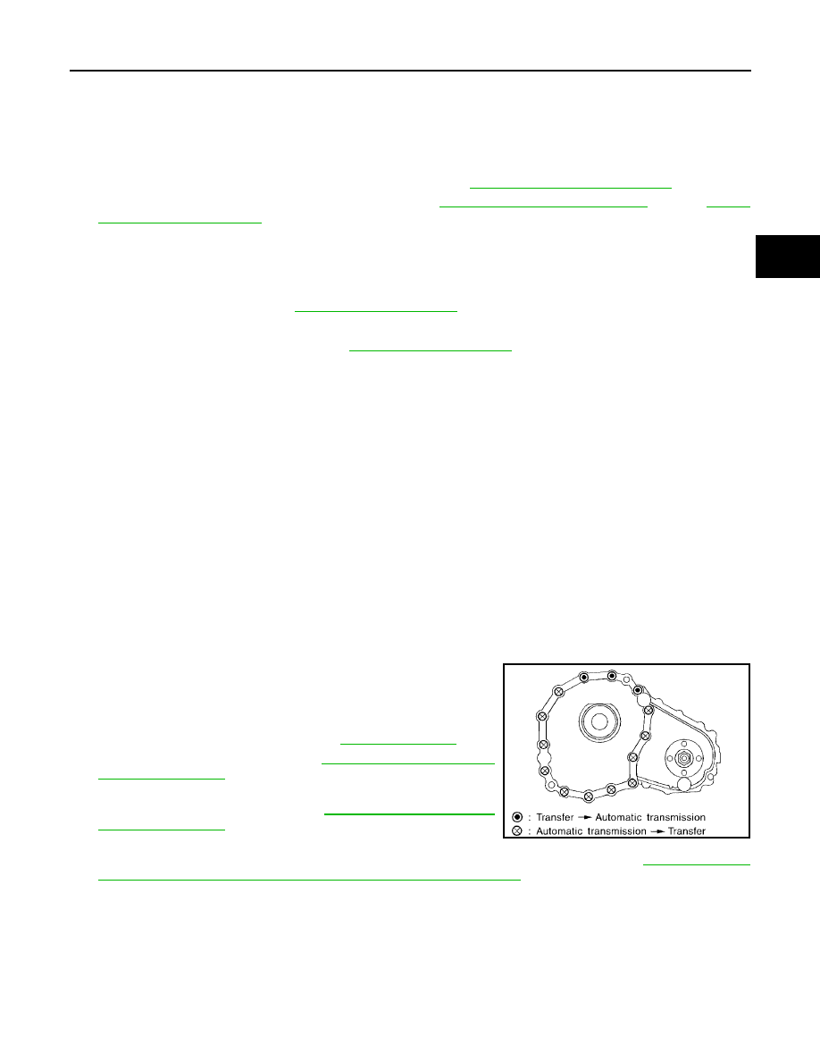
10. Remove the transfer to A/T and A/T to transfer bolts.

WARNING:

Support transfer assembly with suitable jack while removing it.

11. Remove the transfer assembly.

CAUTION:

Do not damage rear oil seal (A/T).

INSTALLATION

Installation is in the reverse order of removal.

Tighten the bolts to specification.

Fill the transfer with new fluid. Refer to

TF-193, "FILLING"

.

Check the transfer fluid. Refer to

TF-193, "FLUID LEAKAGE

AND FLUID LEVEL"

.

Start the engine for one minute. Then stop the engine and
recheck the transfer fluid. Refer to

TF-193, "FLUID LEAKAGE

AND FLUID LEVEL"

.

After the installation, check the 4WD shift indicator pattern. If
NG, adjust the position between the transfer assembly and transfer control unit. Refer to

TF-185, "Precau-

tions for Transfer Assembly and Transfer Control Unit Replacement"

.

Bolt length

: 45 mm (1.77 in)

Tightening torque

: 36 N·m (3.7kg-m, 26 ft-lb)

SMT872C

TF-276

[TX15B]

TRANSFER ASSEMBLY

2005 Pathfinder

Disassembly and Assembly

EDS001LW

COMPONENTS

1.

Baffle plate

2.

Breather tube

3.

Front case

4.

Snap ring

5.

Input oil seal

6.

Self-lock nut

7.

Companion flange

8.

Front oil seal

9.

4LO switch (gray with green paint)

10. ATP switch (black)

11.

Rear case

12. Wait detection switch (gray)

13. Gasket

14. Filler plug

15. Drain plug

16. O-ring

17. Transfer control device

18. Harness bracket

19. Dust cover

20. Rear oil seal

21. Retainer bolt

22. Gasket

SDIA2449E

TRANSFER ASSEMBLY

TF-277

[TX15B]

C

E

F

G

H

I

J

K

L

M

A

B

TF

2005 Pathfinder

1.

Input bearing

2.

Snap ring

3.

Internal gear

4.

Carrier bearing

5.

Sun gear

6.

Needle bearing

7.

Metal bushing

8.

Planetary carrier assembly

9.

L-H sleeve

10. Drive chain

11.

Mainshaft

12. Sprocket

13. 2-4 sleeve

14. Clutch gear

15. Oil pump assembly

16. Retainer

17. Mainshaft rear bearing

18. Front bearing

19. Front drive shaft

20. Rear bearing

21. L-H shift fork

22. L-H shift rod

23. Retaining pin

24. 2-4 shift bracket

25. 2-4 shift fork

26. Fork guide collar

27. 2-4 shift fork spring

28. Retaining ring

29. Snap ring

30. Shift collar

31. Clevis pin

32. Drum cam

33. Control shift rod

34. Spacer

WDIA0207E

TF-278

[TX15B]

TRANSFER ASSEMBLY

2005 Pathfinder

DISASSEMBLY

1.

Remove the drain plug and filler plug.

2.

Remove the transfer control device from the rear case.

3.

Remove the O-ring from the transfer control device.

4.

Remove the self-lock nut from the companion flange, using Tool.

5.

Put a matching mark on top of the front drive shaft in line with
the mark on the companion flange.

CAUTION:

Use paint to make the matching mark on the front drive
shaft. Do not damage the front drive shaft.

6.

Remove the companion flange, using suitable tool.

SDIA2212E

Tool number

: KV40104000 (

)

SDIA2841E

SDIA2779E

WDIA0133E

TRANSFER ASSEMBLY

TF-279

[TX15B]

C

E

F

G

H

I

J

K

L

M

A

B

TF

2005 Pathfinder

7.

Remove the front oil seal from the front case, using Tool.

CAUTION:

Do not damage front case or front drive shaft.

8.

Remove the 4LO switch [gray (with green paint)] and ATP switch
(black) from the front case.

9.

Remove the wait detection switch (gray) from the rear case.

10. Remove the dust cover from the rear case, using suitable tool.

CAUTION:

Do not damage rear case.

11. Remove the rear oil seal from the rear case, using Tool.

CAUTION:

Do not damage rear case or mainshaft.

Tool number

: ST33290001 (J-34286)

SDIA2423E

PDIA0090E

PDIA0091E

PDIA0092E

Tool number

: ST33290001 (J-34286)

SDIA2424E

TF-280

[TX15B]

TRANSFER ASSEMBLY

2005 Pathfinder

12. Remove the input oil seal from the front case, using suitable

tool.

CAUTION:

Do not damage front case, sun gear or input bearing.

13. Remove the retainer bolts and gaskets.

14. Remove the rear case bolts and harness bracket from the rear

case.

15. Separate the front case from the rear case. Then remove the

rear case by prying it up, using suitable tool.

CAUTION:

Do not damage the mating surface.

16. Remove the spacer from the control shift rod.

CAUTION:

Do not drop spacer.

17. Remove the snap ring from the mainshaft, using suitable tool.

PDIA0094E

SDIA2789E

PDIA0299E

PDIA0096E

SDIA2430E

TRANSFER ASSEMBLY

TF-281

[TX15B]

C

E

F

G

H

I

J

K

L

M

A

B

TF

2005 Pathfinder

18. Remove the mainshaft rear bearing from the mainshaft, using

suitable tool.

19. Remove the retainer from the mainshaft.

20. Remove the snap ring from the mainshaft, using suitable tool.

21. Remove the oil pump assembly from the mainshaft.

22. Remove the snap ring from the mainshaft, using suitable tool.

23. Remove the clutch gear from the mainshaft.

24. Remove the snap ring from the L-H shift rod assembly, using

suitable tool.

25. Remove the 2-4 sleeve and 2-4 shift fork assembly from the

mainshaft.

26. Remove the drive chain together with the sprocket and front

drive shaft from the front case.

27. Remove the mainshaft from the sun gear assembly.

28. Remove the L-H shift rod assembly and control shift rod assem-

bly from the front case.

29. Remove the L-H sleeve together with the L-H shift fork from the

planetary carrier assembly.

WDIA0135E

SDIA2461E

SDIA2462E

SDIA2463E

SDIA2464E

TF-282

[TX15B]

TRANSFER ASSEMBLY

2005 Pathfinder

30. Remove the snap ring from the sun gear.

CAUTION:

Do not damage sun gear or input bearing.

31. Press the sun gear assembly and planetary carrier assembly

from the front case, using Tool.

32. Remove the snap ring from the front case.

33. Remove the internal gear from the front case.

34. Remove the snap ring from the front case.

PDIA0099E

Tool number

: KV38100200 (

)

PDIA0100E

PDIA0101E

PDIA0305E

PDIA0103E


Content      ..     455      456      457      458     ..