Nissan Pathfinder (2005 year). Manual - part 455
TROUBLE DIAGNOSIS FOR SYMPTOMS
TF-259
[TX15B]
C
E
F
G
H
I
J
K
L
M
A
B
TF
2005 Pathfinder
DIAGNOSTIC PROCEDURE
1.
CHECK TRANSFER CONTROL UNIT POWER SUPPLY CIRCUIT
1.
Turn ignition switch “OFF”. (Stay for at least 5 seconds.)
2.
Disconnect transfer control unit harness connector.
3.
Check voltage between transfer control unit harness connector
terminals and ground.
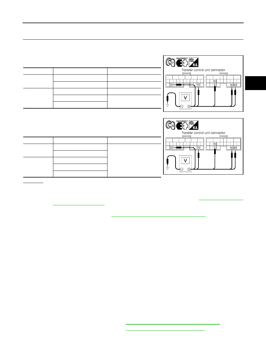
4.
Turn ignition switch “ON”. (Do not start engine.)
5.
Check voltage between transfer control unit harness connector
terminals and ground.
OK or NG
OK
>> GO TO 2.
NG
>> Check the following. If any items are damaged, repair or replace damaged parts.
●
40A fusible link (No. j located in the fuse and fusible link box). Refer to
.
●
10A fuses [No. 21 located in the fuse block-junction block (J/B) and 57 and 58 located in the
fuse and relay box]. Refer to
PG-4, "POWER SUPPLY ROUTING CIRCUIT"
.
●
Harness for short or open between battery and transfer control unit harness connector M152
terminal 19.
●
Harness for short or open between battery and transfer shut off relay 2 harness connector E157
terminal 1 and 3.
●
Harness for short or open between battery and transfer shut off relay 1 harness connector E156
terminal 3.
●
Harness for short or open between ignition switch and transfer control unit harness connector
M152 terminal 25.
●
Harness for short or open between ignition switch and transfer shut off relay 1 harness connec-
tor E156 terminal 1.
●
Harness for short or open transfer shut off relay 2 harness connector E157 terminal 5 and
transfer control unit harness connector M153 terminals 44, 45.
●
Harness for short or open between transfer shut off relay 1 harness connector E156 terminal 5
and transfer control unit harness connector M153 terminals 44, 45.
●
Harness for short or open between transfer shut off relay 2 harness connector E157 terminal 2
and transfer control unit harness connector M153 terminal 40.
●
Harness for open between transfer shut off relay 1 harness connector E156 terminal 2 and
ground.
●
Battery and ignition switch. Refer to
PG-4, "POWER SUPPLY ROUTING CIRCUIT"
.
●
Transfer shut off relay 1, 2. Refer to
TF-224, "COMPONENT INSPECTION"
.
Connector
Terminal (Wire color)
Voltage (Approx.)
M152
19 - Ground
Battery voltage
25 - Ground
0V
M153
40 - Ground
Battery voltage
44 - Ground
0V
45 - Ground
SDIA2799E
Connector
Terminal (Wire color)
Voltage (Approx.)
M152
19 - Ground
Battery voltage
25 - Ground
M153
40 - Ground
44 - Ground
45 - Ground
SDIA2800E