Nissan Pathfinder (2005 year). Manual - part 433
TROUBLE DIAGNOSIS FOR SYSTEM
TF-83
[ATX14B]
C
E
F
G
H
I
J
K
L
M
A
B
TF
2005 Pathfinder
5.
CHECK TRANSFER CONTROL UNIT
Check transfer control unit input/output signal. Refer to
TF-38, "Transfer Control Unit Input/Output Signal Ref-
.
OK or NG
OK
>> GO TO 6.
NG
>> Check transfer control unit pin terminals for damage or loose connection with harness connector.
If any items are damaged, repair or replace damaged parts.
6.
CHECK DTC
Perform the self-diagnosis, after driving a vehicle for a while.
OK or NG
OK
>> Inspection End.
NG
>> Replace transfer control device. Refer to
TF-140, "Removal and Installation"
.
COMPONENT INSPECTION
1.
Remove transfer control device. Refer to
TF-140, "Removal and Installation"
.
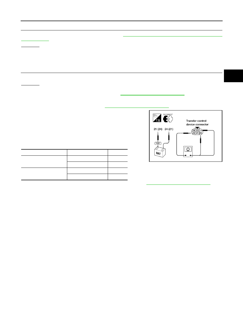
2.
Check operation by applying battery voltage to transfer control
device (actuator motor) terminals 21 and 24.
CAUTION:
●
Do not operate actuator motor for more than 1 second.
●
Change the actuator motor position to “HIGH” when
installing.
●
Be careful not to overheat the harness.
3.
If NG, replace transfer control device (actuator motor). Refer to
TF-140, "Removal and Installation"
.
Terminal
Continuity
Continuity
24 (Battery voltage) - 21
(Ground)
20 - 22
YES
22 - 23
NO
21 (Battery voltage) - 24
(Ground)
22 - 23
YES
20 - 22
NO
LDIA0101E