Nissan Pathfinder (2005 year). Manual - part 421


  Index      Manuals     Nissan Pathfinder (2005 year) - Service and Repair Manual


Search            copyright infringement  


Content      ..     419      420      421      422     ..


Nissan Pathfinder (2005 year). Manual - part 421


DIAGNOSIS SENSOR UNIT

SRS-59

C

D

E

F

G

I

J

K

L

M

A

B

SRS

2005 Pathfinder

DIAGNOSIS SENSOR UNIT

PFP:28556

Removal and Installation

EHS00137

REMOVAL

CAUTION:

Before servicing the SRS, turn the ignition switch off, disconnect both battery cables and wait at
least 3 minutes.

1.

Disconnect the connectors for each air bag module and seat belt pre-tensioner.

2.

Remove center console. Refer to

IP-10, "INSTRUMENT PANEL ASSEMBLY"

.

3.

Disconnect diagnosis sensor unit connectors.
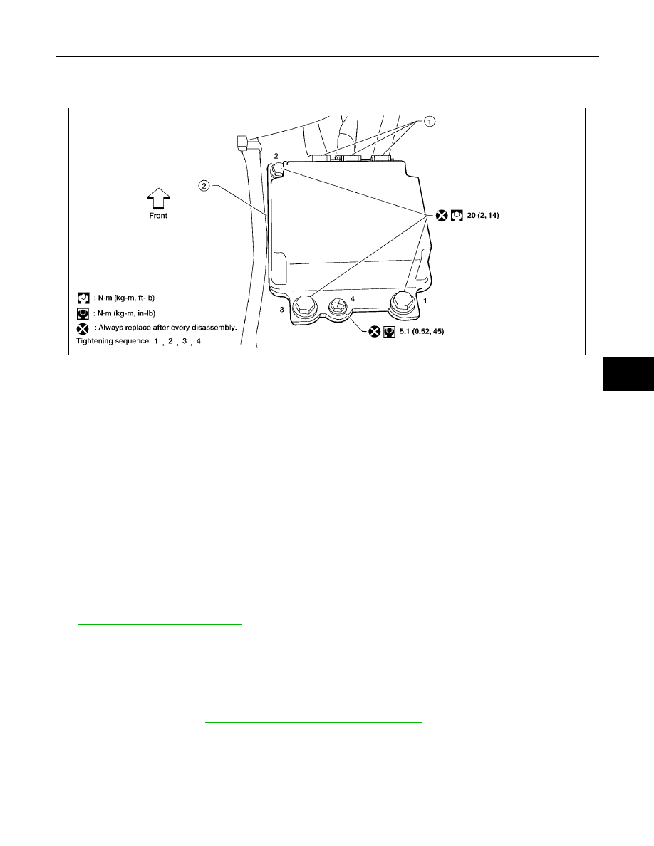
4.

Remove bolts from the diagnosis sensor unit.

CAUTION:

Do not use old bolts; replace with new bolts.

Check diagnosis sensor unit bracket to ensure it is free of deformities, dents, cracks or rust. If it
shows any visible signs of damage, replace with new one.

Replace diagnosis sensor unit if it has been dropped or sustained an impact.

INSTALLATION

Installation is in the reverse order of removal.

After the work is completed, perform self-diagnosis to check that no malfunction is detected. Refer to

SRS-21, "SRS Operation Check"

.

CAUTION:

The diagnosis sensor unit must always be installed with the arrow mark "

" pointing toward the

front of the vehicle for proper operation.

ECU DISCRIMINATED NO.

After replacing the diagnosis sensor unit, confirm that the diagnosis sensor unit identification is correct for the
vehicle as equipped. Refer to

SRS-19, "CONSULT-II Function (AIR BAG)"

.

LHIA0092E

1.

Diagnosis sensor unit connectors

2.

Diagnosis sensor unit

SRS-60

OCCUPANT CLASSIFICATION SYSTEM CONTROL UNIT

2005 Pathfinder

OCCUPANT CLASSIFICATION SYSTEM CONTROL UNIT

PFP:98852

Removal and Installation

EHS00138

The occupant classification control unit, occupant classification (pressure) sensor, and bladder are an integral
part of the front passenger seat cushion and are replaced as an assembly. Refer to

SE-93, "REMOVAL"

to

remove the seat, and

SE-94, "SEAT CUSHION TRIM AND PAD"

to replace the seat cushion.

DISPOSAL OF AIR BAG MODULE AND SEAT BELT PRE-TENSIONER

SRS-61

C

D

E

F

G

I

J

K

L

M

A

B

SRS

2005 Pathfinder

DISPOSAL OF AIR BAG MODULE AND SEAT BELT PRE-TENSIONER

PFP:00014

Caution for Air Bag Module and Seat Belt Pre-tensioner

EHS00139

Before disposing of air bag module, seat belt pre-tensioner or vehicle equipped with such systems, deploy
the systems. If such systems have already been deployed due to an accident, dispose of them as indi-
cated in 

SRS-67, "DISPOSING OF AIR BAG MODULE AND SEAT BELT PRE-TENSIONER"

.

When deploying the air bag module or seat belt pre-tensioner, always use the Special Service Tool
Deployment tool [KV99106400 (J-38381)].

When deploying the air bag module or seat belt pre-tensioner, stand at least 5 m (16 ft) away from the
component being deployed.

When deploying air bag module or seat belt pre-tensioner, a fairly loud noise is made, followed by smoke
being released. The smoke is not poisonous, however, be careful not to inhale smoke since it irritates the
throat and can cause choking.

Only deploy one air bag module or seat belt pre-tensioner at a time.

Due to heat, leave deployed air bag module unattended for at least 30 minutes after deployment. Leave
deployed seat belt pre-tensioner unattended for at least 10 minutes after deployment.

Be sure to wear gloves when handling a deployed air bag module or seat belt pre-tensioner.

Never apply water to the deployed air bag module or seat belt pre-tensioner.

Wash your hands thoroughly after finishing work.

Place the vehicle outdoors with an open space of at least 6 m (20 ft) on all sides when deploying air bag
module or seat belt pre-tensioner while mounted in vehicle.

Use a voltmeter to make sure the vehicle battery is fully charged.

Do not dispose of the air bag module or seat belt pre-tensioner undeployed.

CHECKING DEPLOYMENT TOOL
Connecting to Battery

CAUTION:

The battery must show voltage of 9.6V or more.
Remove the battery from the vehicle and place it on dry wood blocks
approximately 5 m (16 ft) away from the vehicle.

Wait 3 minutes after the vehicle battery is disconnected before
proceeding.

Connect red clip of deployment tool to battery positive terminal
and black clip to negative terminal.

Make sure the polarity is correct. The right side lamp in the tool
marked “deployment tool power” should glow with a green
light. If the right side lamp glows red, reverse the connections
to the battery.

Deployment Tool Check

Place the deployment tool switch to the ON position. The left side
lamp in the tool, marked “air bag connector voltage” should illumi-
nate. If it does not illuminate, replace the tool.

SRS019

SBF266H

SRS-62

DISPOSAL OF AIR BAG MODULE AND SEAT BELT PRE-TENSIONER

2005 Pathfinder

Air Bag Deployment Tool Lamp Illumination Chart (Battery connected)

*: If this lamp glows red, the tool is connected to the battery incorrectly. Reverse the connections and make sure the lamp glows green.

DEPLOYMENT PROCEDURES FOR AIR BAG MODULE (OUTSIDE OF VEHICLE)

Unless the vehicle is being scrapped, deploying the air bag in the
vehicle is not recommended. This may cause damage to the vehicle
interior.
Anchor the deployment Tool in a vise secured to a firm foundation
during deployment.

Deployment of Driver Air Bag Module (Outside of vehicle)

1.

Using wire, secure air bag module to the Tool at two places.

CAUTION:

Use wire of at least 1 mm (0.04 in) diameter.

2.

Firmly secure Tool with air bag module attached, in a vise.

3.

Connect deployment Tool A to air bag module connector using
Tool B.

4.

Connect red clip of Tool to battery positive terminal and black
clip to negative terminal.

5.

The lamp on the right side of the tool, marked “deployment tool
power”, should glow green, not red.

6.

Press the button on the deployment tool. The left side lamp on
the tool, marked “air bag connector voltage”, will illuminate and
the air bag module will deploy.

Switch operation

Left side lamp, green*

“AIR BAG CONNECTOR

VOLTAGE”

Right side lamp, green*

“DEPLOYMENT TOOL

POWER”

OFF

OFF

ON

ON

ON

ON

Tool number:

KV99105300 (J-41246)

SRS232-C

Tool number:

KV99105300 (J-41246)

Tool number:

KV99105300 (J-41246)

LHIA0037E

Tool number:

A: KV99106400 (J-38381)

B: KV99105300 (J-38381-80)

WHIA0120E

Tool number:

KV99106400 (J-38381)

LHIA0038E

DISPOSAL OF AIR BAG MODULE AND SEAT BELT PRE-TENSIONER

SRS-63

C

D

E

F

G

I

J

K

L

M

A

B

SRS

2005 Pathfinder

CAUTION:

When deploying the driver air bag module, stand at least 5 m (16 ft) away from the air bag module.

Deployment of Front Passenger Air Bag Module (Outside of vehicle)

1.

Firmly secure the Tool A in a vise, then secure Tool B to Tool A.

2.

Match the two holes in the Tool and front passenger air bag
module and fix them with two bolts.

3.

Connect deployment Tool A to front passenger air bag module
using Tool B.

4.

Connect red clip of the Tool to battery positive terminal and
black clip to negative terminal.

5.

The lamp on the right side of the Tool, marked “deployment tool
power”, should glow green, not red.

6.

Press the button on the Tool. The left side lamp on the tool,
marked “air bag connector voltage”, will illuminate and the air
bag module will deploy.

CAUTION:

When deploying the front passenger air bag module, do not
stand on the deploying side.

Stand at least 5 m (16 ft) away from the air bag module.

Tool number:

A: KV99105300 (J-41246)

B: J-39401-100

LHIA0040E

Tool number:

J-39401-100

LHIA0041E

Tool number:

A: KV99106400 (J-38381)

B: KV99105300 (J-38381-80)

LHIA0050E

Tool number:

KV99106400 (J-38381)

SRS020-B

SRS-64

DISPOSAL OF AIR BAG MODULE AND SEAT BELT PRE-TENSIONER

2005 Pathfinder

Deployment of Front Side Air Bag Module (Outside of vehicle)

1.

Make 6.5 mm (0.256 in) diameter holes in air bag module
bracket [SST: KV99105300 (J-41246)] at the positions shown.

2.

Firmly secure air bag module bracket [SST: KV99105300 (J-
41246)] in a vise.

3.

Insert the stud bolts of side air bag module into the two holes in
air bag module bracket (held in vise) and fix them with two M6
nuts.

CAUTION:

Side air bag module should be secured to air bag module
bracket [SST: KV99105300 (J-41246)] in a vise with stud bolt
side facing down.

4.

Connect deployment tool [SST: KV99106400 (J-38381)] connec-
tor to connector on air bag module using deployment tool
adapter [SST: KV99109000 (J-44230)].

5.

Connect red clip of deployment tool to battery positive terminal
and black clip to negative terminal.

6.

The lamp on the right side of the tool, marked “deployment tool
power”, should glow green, not red.

7.

Press the button on the deployment tool. The left side lamp on
the tool, marked “air bag connector voltage”, will illuminate and
the air bag module will deploy.

CAUTION:

When deploying the front side air bag module, stand at
least 5 m (16 ft) away from the air bag module.

Deployment of Side Curtain Air Bag Module (Outside of vehicle)

NOTE:
The side curtain air bag module has a front and rear inflator that are connected by the fabric of the side curtain
air bag. Follow the procedure to cut the fabric from the inflators, and then follow the procedure to deploy each
inflator.

SRS490-B

SHIA0197E

WHIA0045E

WHIA0046E

DISPOSAL OF AIR BAG MODULE AND SEAT BELT PRE-TENSIONER

SRS-65

C

D

E

F

G

I

J

K

L

M

A

B

SRS

2005 Pathfinder

1.

Cut the inflator from side curtain air bag module.

2.

Connect deployment tool [SST: KV99106400 (J-38381)] to the
inflator using deployment tool adapter (J-38381-80).

3.

Put the inflator connected with the deployment tool [SST:
KV99106400 (J-38381)] into a tire without a wheel.

4.

Put the tire with the inflator onto another tire without wheel. Add
an additional tire without a wheel and then a tire mounted on a
wheel on top.

CAUTION:

Tie all tires together with a strap in order to keep them
standing.

5.

Connect red clip of deployment tool to battery positive terminal
and black clip to negative terminal.

6.

The lamp on the right side of the tool, marked “deployment tool
power”, should glow green, not red.

7.

Press the button on the deployment tool. The left side lamp on
the tool, marked “air bag connector voltage”, will illuminate and the air bag module will deploy.

CAUTION:

When deploying the side curtain air bag module, stand at least 5 m (16 ft) away from the side cur-
tain air bag module.

8.

Repeat this procedure to deploy the second inflator.

SHIA0198E

WHIA0073E

SHIA0201E

WHIA0048E

SRS-66

DISPOSAL OF AIR BAG MODULE AND SEAT BELT PRE-TENSIONER

2005 Pathfinder

DEPLOYMENT PROCEDURES FOR SEAT BELT PRE-TENSIONER (OUTSIDE OF VEHICLE)

1.

Firmly grip pre-tensioner in a vise and cut off the webbing.

2.

Connect deployment tool [SST: KV99106400 (J-38381)] connec-
tor to front seat belt pre-tensioner using deployment tool adapter
(J-38381-80).

3.

Connect red clip of deployment tool to battery positive terminal
and black clip to negative terminal.

4.

The lamp on the right side of the tool, marked “deployment tool
power”, should glow green, not red.

5.

Press the button on the deployment tool. The left side lamp on
the tool, marked “seat belt pre-tensioner connector voltage”, will
illuminate and the seat belt pre-tensioner will deploy.

CAUTION:

When deploying the front seat belt pre-tensioner, stand at
least 5 m (16 ft) away from the seat belt pre-tensioner.

DEPLOYMENT OF AIR BAG MODULES AND SEAT BELT PRE-TENSIONERS WHILE
MOUNTED IN VEHICLE

When disposing of a vehicle, deploy air bag modules and seat belt pre-tensioners while they are mounted in
vehicle.

CAUTION:

When deploying air bag module or seat belt pre-tensioner, ensure vehicle is empty.

1.

Disconnect both the vehicle battery cables and wait 3 minutes.

2.

Disconnect all air bag module and seat belt pre-tensioner harness connectors.

3.

Connect deployment tool [SST: KV99106400 (J-38381)] to air bag module or seat belt pre-tensioner.
For driver air bag module, use deployment tool adapter (J-38381-80).
For front passenger air bag module, use deployment tool adapter (J-38381-65).
For side curtain air bag module, use deployment tool adapter (J-38381-80).
For side air bag module, use deployment tool adapter [SST: KV99109000 (J-44230)].

WHIA0122E

LHIA0039E

SRS242


Content      ..     419      420      421      422     ..