Nissan Pathfinder (2005 year). Manual - part 408
AUTOMATIC DRIVE POSITIONER
SE-59
C
D
E
F
G
H
J
K
L
M
A
B
SE
2005 Pathfinder
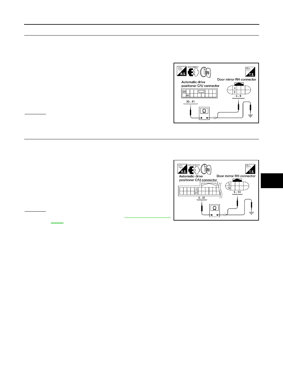
3.
CHECK HARNESS CONTINUITY 1
1.
Turn ignition OFF.
2.
Disconnect automatic drive positioner control unit and door mirror RH.
3.
Check continuity between automatic drive positioner control unit connector M34 terminals 33, 41 and door
mirror RH connector D107 terminals 4, 9.
4.
Check continuity between automatic drive positioner control unit
connector M34 terminals 33, 41 and ground.
OK or NG
OK
>> GO TO 4.
NG
>> Repair or replace harness.
4.
CHECK HARNESS CONTINUITY 2
1.
Disconnect automatic drive positioner control unit and door mirror RH.
2.
Check continuity between automatic drive positioner control unit connector M33 terminals 5, 21 and door
mirror RH connector D107 terminals 5, 10.
3.
Check continuity between automatic drive positioner control unit
connector M33 terminals 5, 21 and ground.
OK or NG
OK
>> Replace door mirror RH. Refer to
.
NG
>> Repair or replace harness.
33 - 4
: Continuity should exist.
41 - 9
: Continuity should exist.
33 - Ground
: Continuity should not exist.
41 - Ground
: Continuity should not exist.
LIIA1771E
5 - 10
: Continuity should exist.
21 - 5
: Continuity should exist.
5 - Ground
: Continuity should not exist.
21 - Ground
: Continuity should not exist.
LIIA1772E