Nissan Pathfinder (2005 year). Manual - part 406
AUTOMATIC DRIVE POSITIONER
SE-43
C
D
E
F
G
H
J
K
L
M
A
B
SE
2005 Pathfinder
4.
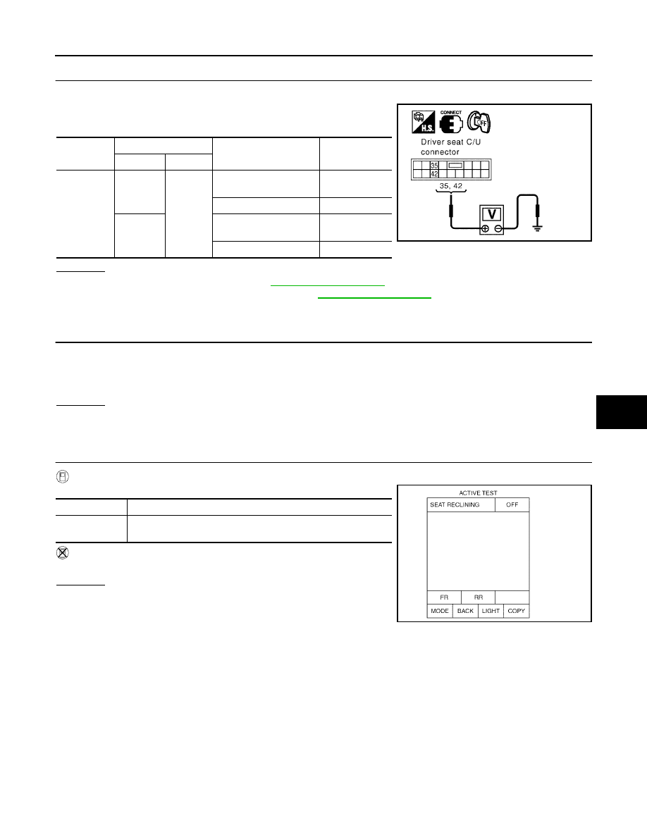
CHECK DRIVER SEAT CONTROL UNIT OUTPUT SIGNAL
1.
Connect the driver seat control unit and sliding motor LH.
2.
Check voltage between driver seat control unit connector and
ground.
OK or NG
OK
>> Replace sliding motor. Refer to
.
NG
>> Replace driver seat control unit. Refer to
.
Reclining Motor LH Circuit Inspection
EIS0045G
1.
CHECK SEAT RECLINING MECHANISM
Check the following.
●
Operation malfunction caused by an interference with the center pillar or center console
●
Operation malfunction and interference with other parts by poor installation
OK or NG
OK
>> GO TO 2.
NG
>> Repair or replace the malfunctioning part and check again.
2.
CHECK FUNCTION
With CONSULT-II
Check operation with “SEAT RECLINING” in ACTIVE TEST.
Without CONSULT-II
GO TO 3.
OK or NG
OK
>> Reclining motor LH circuit is OK.
NG
>> GO TO 3.
Connector
Terminals
Condition
Voltage (V)
(Approx.)
(+)
(–)
P3
35
Ground
Sliding switch ON
(FORWARD operation)
Battery voltage
Other than above
0
42
Sliding switch ON
(BACKWARD operation)
Battery voltage
Other than above
0
PIIA4801E
Test item
Description
SEAT
RECLINING
The reclining motor LH is activated by receiving the drive signal.
PIIA0268E