Index Manuals Nissan Pathfinder (2005 year) - Service and Repair Manual
Search copyright infringement
Content .. 402 403 404 405 ..
Nissan Pathfinder (2005 year). Manual - part 404
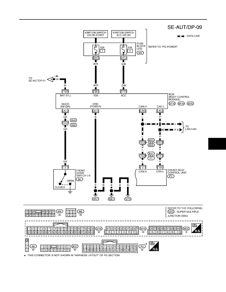
AUTOMATIC DRIVE POSITIONER
SE-27
C
D
E
F
G
H
J
K
L
M
A
B
SE
2005 Pathfinder
WIWA0564E