Nissan Pathfinder (2005 year). Manual - part 398


  Index      Manuals     Nissan Pathfinder (2005 year) - Service and Repair Manual


Search            copyright infringement  


Content      ..     396      397      398      399     ..


Nissan Pathfinder (2005 year). Manual - part 398


STARTING SYSTEM

SC-11

C

D

E

F

G

H

I

J

L

M

A

B

SC

2005 Pathfinder

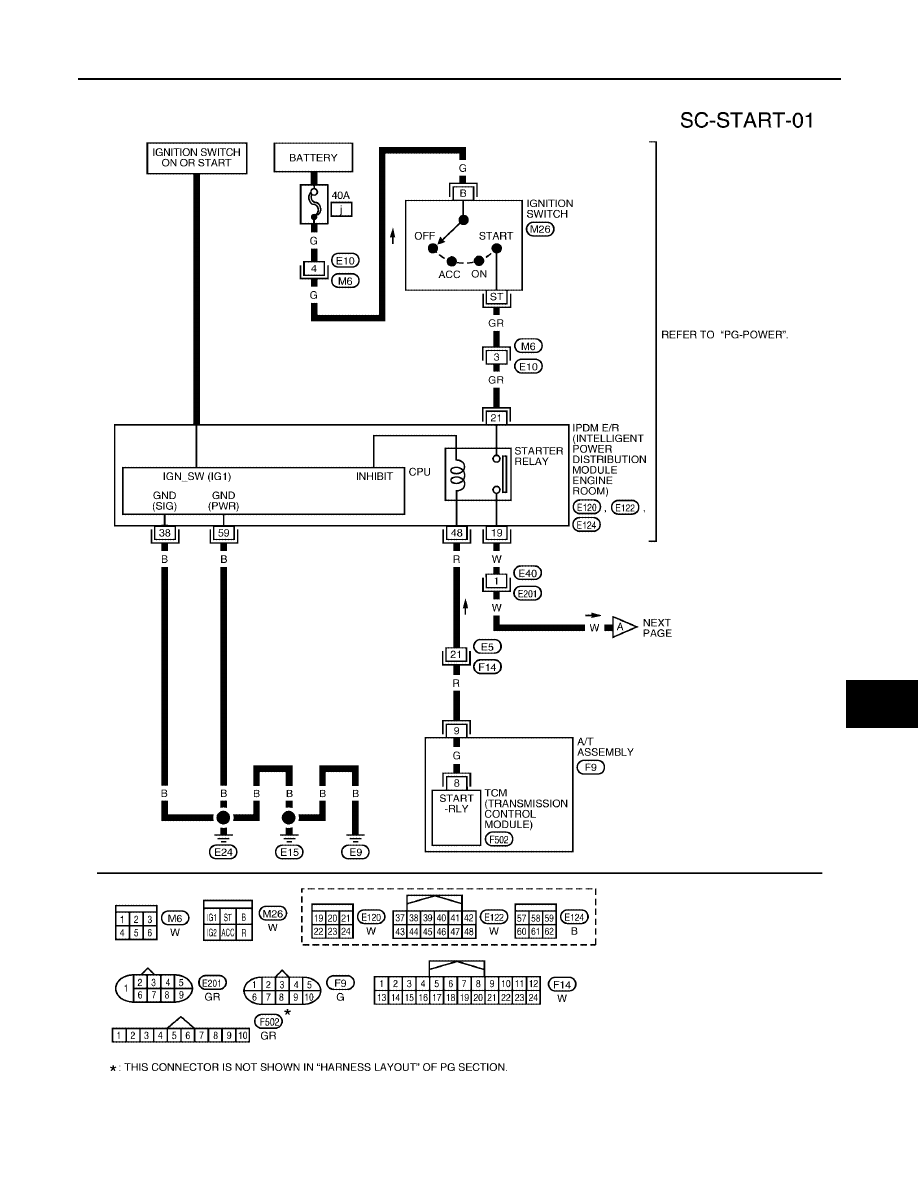
Wiring Diagram — START —

EKS009IZ

WKWA1961E

SC-12

STARTING SYSTEM

2005 Pathfinder

WKWA1963E

STARTING SYSTEM

SC-13

C

D

E

F

G

H

I

J

L

M

A

B

SC

2005 Pathfinder

Trouble Diagnoses with Battery/Starting/Charging System Tester

EKS009J0

NOTE:
To ensure a complete and thorough diagnosis, the battery, starter and generator test segments must be done
as a set from start to finish.

1.

Turn off all loads on the vehicle electrical system.

2.

Perform battery test with Battery/Starting/Charging system
tester. Refer to

SC-13, "Trouble Diagnoses with Battery/Starting/

Charging System Tester"

.

3.

Press “ENTER” to begin the starting system test.

4.

Start the engine.

5.

Diagnosis result is displayed on the tester. Refer to

SC-13,

"DIAGNOSTIC RESULT ITEM CHART"

.

NOTE:

If the starter performs normally but the engine does not start,
perform engine diagnosis.

For intermittent “NO CRANK” or “NO STARTER OPERA-
TION” incidents, refer to

SC-16, "DIAGNOSTIC PROCE-

DURE 2"

.

DIAGNOSTIC RESULT ITEM CHART

SEL408X

SEL409X

SEL410X

Diagnostic item

Service procedure

CRANKING VOLTAGE NORMAL

Go to

SC-14, "WORK FLOW"

.

CRANKING VOLTAGE LOW

CHARGE BATTERY

Perform the slow battery charging procedure. (Initial rate of charge is 10A for 12 hours.) Per-
form battery test again with Battery/Starting/Charging system tester. Refer to

SC-13, "Trouble

Diagnoses with Battery/Starting/Charging System Tester"

.

REPLACE BATTERY

Before replacing battery, clean the battery cable clamps and battery posts. Perform battery
test again with Battery/Starting/Charging system tester. Refer to

SC-13, "Trouble Diagnoses

with Battery/Starting/Charging System Tester"

. If second test result is “REPLACE BAT-

TERY”, then do so. Perform battery test again to confirm repair.

SC-14

STARTING SYSTEM

2005 Pathfinder

WORK FLOW

*1

SC-13

*2

SC-15

*3

SC-16

*4

SC-16

WKIA2104E

STARTING SYSTEM

SC-15

C

D

E

F

G

H

I

J

L

M

A

B

SC

2005 Pathfinder

DIAGNOSTIC PROCEDURE 1
Check Terminal "2" Circuit

1.

CHECK POWER SUPPLY FOR STARTER MOTOR “2” TERMINAL

1.

Remove the fuel pump fuse.

2.

Crank or start the engine (where possible) until the fuel pressure is released.

3.

Turn the ignition switch OFF.

4.

Check that the starter motor connector F27 connection is clean and tight.

5.

Check voltage between starter motor connector F27 terminal 2
and ground using a digital circuit tester.

OK or NG

OK

>> GO TO 2.

NG

>> Check harness between the battery and the starter

motor for open circuit.

2.

CHECK BATTERY CABLE CONNECTION QUALITY (VOLTAGE DROP TEST)

Check voltage between starter motor connector F27 terminal 2 and
battery positive terminal using a digital circuit tester.

OK or NG

OK

>> GO TO 3.

NG

>> Check harness between the battery and the starter

motor for poor continuity.

3.

CHECK STARTER MOTOR GROUND CIRCUIT (VOLTAGE DROP TEST)

Check voltage between starter motor case and battery negative ter-
minal using a digital circuit tester.

OK or NG

OK

>> Starter motor “2” terminal circuit is OK. Further inspec-

tion is necessary. Refer to

SC-14, "WORK FLOW"

.

NG

>> Check harness between the starter motor case and

ground for poor continuity.

Battery voltage should
exist.

WKIA2105E

Ignition switch in
START.

: Less than 0.5V

WKIA2106E

Ignition switch in
START.

: Less than 0.2V

WKIA2107E

SC-16

STARTING SYSTEM

2005 Pathfinder

DIAGNOSTIC PROCEDURE 2
Check Terminal "1" Circuit

1.

CHECK POWER SUPPLY FOR STARTER MOTOR “1” TERMINAL

1.

Remove the fuel pump fuse.

2.

Crank or start the engine (where possible) until the fuel pressure is released.

3.

Turn the ignition switch OFF.

4.

Disconnect starter motor connector F28.

5.

Check voltage between starter motor connector F28 terminal 1
and ground using a digital circuit tester.

OK or NG

OK

>> GO TO 2.

NG

>> Check the following.

40A fusible link (letter , located in fuse and fusible
link box)

Ignition switch

Starter relay [within the intelligent power distribution module engine room (IPDM E/R)]

Harness for open or short

2.

CHECK “1” TERMINAL CONNECTION QUALITY (VOLTAGE DROP TEST)

1.

Turn the ignition switch OFF.

2.

Connect starter motor connector F28.

3.

Check voltage between starter motor connector F28 terminal 1
and battery positive terminal using a digital circuit tester.

OK or NG

OK

>> Starter motor “1” terminal circuit is OK. Further inspec-

tion is necessary. Refer to

SC-14, "WORK FLOW"

.

NG

>> Check harness between the battery and the starter

motor “1” terminal for poor continuity.

Ignition switch in
START.

: Battery voltage

WKIA3181E

Ignition switch in
START.

: Less than 1V

WKIA3182E

STARTING SYSTEM

SC-17

C

D

E

F

G

H

I

J

L

M

A

B

SC

2005 Pathfinder

MINIMUM SPECIFICATION OF CRANKING VOLTAGE REFERENCING COOLANT TEMPERA-
TURE

Removal and Installation

EKS009J1

REMOVAL

1.

Disconnect the negative battery terminal.

2.

Remove engine undercover, using power tools.

3.

Remove exhaust manifold cover from exhaust manifold (right bank) to gain access to starter cover bolts.
Refer to

EX-4, "REMOVAL"

.

4.

Remove starter cover bolts and starter cover.

Engine coolant temperature

Voltage V

30

°

C to

20

°

C (

22

°

F to

4

°

F)

8.4

19

°

C to

10

°

C (

2

°

F to 14

°

F)

8.9

9

°

C to 0

°

C (16

°

F to 32

°

F)

9.3

More than 1

°

C (More than 34

°

F)

9.7

WKIA3190E

1.

Starter cover

2.

Starter motor assembly

3.

Starter cover plate (rear)

4.

Transmission housing

SC-18

STARTING SYSTEM

2005 Pathfinder

5.

Disconnect terminal "1" connector and terminal "2" nut.

6.

Remove the two starter bolts, using power tools.

7.

Remove the starter.

INSTALLATION

To installation is in the reverse order of removal.

CAUTION:

Be sure to tighten terminal "2" nut carefully.

WKIA3189E

Terminal "2" nut

: 10.8 N·m (1.1 kg-m, 8 ft-lb)


Content      ..     396      397      398      399     ..