Nissan Pathfinder (2005 year). Manual - part 378
 

  Index      Manuals     Nissan Pathfinder (2005 year) - Service and Repair Manual


Search            copyright infringement  


Content      ..     376      377      378      379     ..


Nissan Pathfinder (2005 year). Manual - part 378


REAR PROPELLER SHAFT

PR-11

C

E

F

G

H

I

J

K

L

M

A

B

PR

2005 Pathfinder

INSPECTION

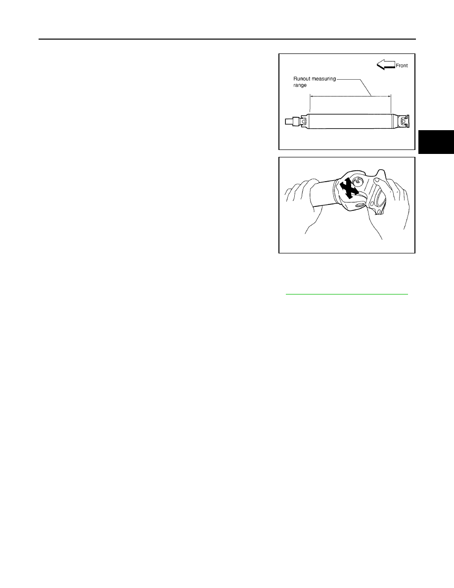
Inspect the propeller shaft runout. If runout exceeds the limit,
replace the propeller shaft assembly.

While holding the flange yoke on one side, check axial play of
the joint as shown. If the journal axial play exceeds the specifi-
cation, repair or replace the journal parts.

Check the propeller shaft tube for dents or cracks. If damage is
detected, replace the propeller shaft assembly.

INSTALLATION

Installation is in the reverse order of removal.

After installation, check for vibration by driving the vehicle. Refer to

PR-3, "NVH Troubleshooting Chart"

.

CAUTION:

Do not reuse the bolts and nuts. Always install new ones.

Propeller shaft runout limit

4x2

: 1.02 mm (0.0402 in) or less

4x4

: 0.6 mm (0.024 in) or less

LDIA0121E

Journal axial play

: 0.02 mm (0.0008 in) or less

LDIA0117E

PR-12

REAR PROPELLER SHAFT

2005 Pathfinder

Disassembly and Assembly

EDS001H3

DISASSEMBLY
Journal

1.

Put matching marks on the rear propeller shaft and flange yoke
as shown.

CAUTION:

For matching marks use paint. Never damage the rear pro-
peller shaft or flange yoke.

2.

Remove the snap rings.

3.

Push out and remove the journal bearings by lightly tapping the
flange yoke with a hammer, taking care not to damage the jour-
nal or flange yoke hole.

NOTE:
Put marks on the disassembled parts so that they can be rein-
stalled in their original positions from which they were removed.

4.

Push out and remove the remaining journal bearings at the
opposite side by lightly tapping the flange yoke with a hammer,
taking care not to damage the journal or flange yoke hole.
NOTE:
Put marks on the disassembled parts so that they can be rein-
stalled in their original positions from which they were removed.

SPD128

APD011

SPD732

SPD131

REAR PROPELLER SHAFT

PR-13

C

E

F

G

H

I

J

K

L

M

A

B

PR

2005 Pathfinder

ASSEMBLY
Journal

1.

Assemble the journal bearings. Apply multipurpose grease on
the bearing inner surface.
NOTE:
During assembly, use caution so that the needle bearings do not
fall down.

2.

Select snap rings that will provide the specified play in an axial
direction of the journal, and install them. Refer to

PR-15, "Snap

Ring"

.

NOTE:
Select snap rings with a difference in thickness at both sides
within 0.02 mm (0.0008 in).

3.

Adjust the thrust clearance between the bearing and snap ring
to zero by tapping the yoke.

4.

Make sure that the journal moves smoothly and is below the
joint flex effort specification.

WPD019

APD012

SPD732

Joint flex effort

: 2.26 N·m (0.23 kg-m, 20 in-lb) or less

LDIA0119E

PR-14

SERVICE DATA AND SPECIFICATIONS (SDS)

2005 Pathfinder

SERVICE DATA AND SPECIFICATIONS (SDS)

PFP:00030

General Specifications

EDS001H4

4X2 Model

4X4 Model

Applied model

VQ40DE

Propeller shaft model

2S1330 (aluminum tube)

Number of joints

2

Coupling method with rear final drive

Flange type

Coupling method with transmission

Sleeve type

Shaft length (Spider to spider)

1422.2 mm (55.99 in)

Shaft outer diameter

127.6 mm (5.02 in)

Journal axial play

0.02 mm (0.0008 in) or less

Propeller shaft runout limit

1.02 mm (0.0402 in) or less

Propeller shaft joint flex effort

2.26 N·m (0.23 kg-m, 20 in-lb) or less

Applied model

VQ40DE

Propeller shaft model

Front

Rear

Full time 4x4

Part time 4x4

2F1310

2S1330 (steel tube)

Number of joints

2

Coupling method with front final drive

Flange type

Coupling method with transfer

Flange type

Sleeve type

Shaft length (Spider to spider)

696 mm (27.40 in)

917.8 mm

(36.13 in)

952.8 mm
(37.51 in)

Shaft outer diameter

63 5 mm (2.5 in)

76.2 mm (3.00 in)

Journal axial play

0.02 mm (0.0008 in) or less

Propeller shaft runout limit

0.6 mm (0.024 in) or less

Propeller shaft joint flex effort

1.96 N·m (0.20 kg-m, 17 in-lb)

or less

2.26 N·m (0.23 kg-m, 20 in-lb)

or less

SERVICE DATA AND SPECIFICATIONS (SDS)

PR-15

C

E

F

G

H

I

J

K

L

M

A

B

PR

2005 Pathfinder

Snap Ring

EDS001H5

Model 2F1310 and 2S1330 (4WD)

Unit: mm (in)

*Always check with the Parts Department for the latest parts information.

Model 2S1330 (2WD)

Unit: mm (in)

*Always check with the Parts Department for the latest parts information.

Thickness

Color

Part Number*

1.99 (0.0783)

White

37146-C9400

2.02 (0.0795)

Yellow

37147-C9400

2.05 (0.0807)

Red

37148-C9400

2.08 (0.0819)

Green

37149-C9400

2.11 (0.0831)

Blue

37150-C9400

2.14 (0.0843)

Light brown

37151-C9400

2.17 (0.0854)

Black

37152-C9400

2.20 (0.0866)

No paint

37153-C9400

Thickness

Color

Part Number*

1.600 - 1.638 (0.0630 - 0.0645)

Black

37146-7S000

1.549 - 1.588 (0.0610 - 0.0625)

Black

37147-7S000

1.524 - 1.562 (0.0600 - 0.0615)

Black

37148-7S000

1.499 - 1.537 (0.0590 - 0.0605)

Black

37149-7S000

PR-16

SERVICE DATA AND SPECIFICATIONS (SDS)

2005 Pathfinder

PS-1

POWER STEERING SYSTEM

G STEERING

CONTENTS

C

D

E

F

H

I

J

K

L

M

SECTION

A

B

PS

2005 Pathfinder

PRECAUTIONS .......................................................... 2

Precautions for Supplemental Restraint System
(SRS) “AIR BAG” and “SEAT BELT PRE-TEN-
SIONER” .................................................................. 2
Precautions for Steering System .............................. 2

PREPARATION ........................................................... 3

Special Service Tools (SST) ..................................... 3
Commercial Service Tools ........................................ 4

NOISE, VIBRATION, AND HARSHNESS (NVH)
TROUBLESHOOTING ................................................ 5

NVH Troubleshooting Chart ..................................... 5

POWER STEERING FLUID ........................................ 6

Checking Fluid Level ................................................ 6
Checking Fluid Leakage ........................................... 6
Air Bleeding Hydraulic System ................................. 6

STEERING WHEEL .................................................... 8

On-Vehicle Inspection and Service .......................... 8

CHECKING CONDITION OF INSTALLATION ...... 8
CHECKING STEERING WHEEL PLAY ................ 8
CHECKING NEUTRAL POSITION ON STEER-
ING WHEEL .......................................................... 8
CHECKING STEERING WHEEL TURNING
FORCE .................................................................. 8
CHECKING FRONT WHEEL TURNING ANGLE..... 9

Removal and Installation .......................................... 9

REMOVAL ............................................................. 9
INSTALLATION ..................................................... 9

STEERING COLUMN ............................................... 10

Removal and Installation ........................................ 10

REMOVAL ........................................................... 10
INSPECTION AFTER REMOVAL ........................11
INSTALLATION ....................................................11

INSPECTION AFTER INSTALLATION ................ 13

Disassembly and Assembly .................................... 13

DISASSEMBLY ................................................... 13
ASSEMBLY ......................................................... 14
INSPECTION AFTER ASSEMBLY ...................... 14

POWER STEERING GEAR AND LINKAGE ............ 15

Removal and Installation ........................................ 15

REMOVAL ........................................................... 15
INSTALLATION ................................................... 16
INSPECTION AFTER INSTALLATION ................ 16

Disassembly and Assembly .................................... 17

DISASSEMBLY ................................................... 17
INSPECTION AFTER DISASSEMBLY ................ 18
ASSEMBLY ......................................................... 18

POWER STEERING OIL PUMP ............................... 20

On-Vehicle Inspection and Service ......................... 20

CHECKING RELIEF OIL PRESSURE ................ 20

Removal and Installation ........................................ 20

REMOVAL ........................................................... 20
INSTALLATION ................................................... 20

Disassembly and Assembly .................................... 21

INSPECTION BEFORE DISASSEMBLY ............. 21
DISASSEMBLY ................................................... 21
INSPECTION AFTER DISASSEMBLY ................ 22
ASSEMBLY ......................................................... 22

HYDRAULIC LINE .................................................... 23

Removal and Installation ........................................ 23

SERVICE DATA AND SPECIFICATIONS (SDS) ...... 25

Steering Wheel ....................................................... 25
Steering Column ..................................................... 25
Steering Outer Socket and Inner Socket ................ 25
Steering Gear ......................................................... 26
Oil Pump ................................................................. 26
Steering Fluid .......................................................... 26

PS-2

PRECAUTIONS

2005 Pathfinder

PRECAUTIONS

PFP:00001

Precautions for Supplemental Restraint System (SRS) “AIR BAG” and “SEAT
BELT PRE-TENSIONER”

EGS000S4

The Supplemental Restraint System such as “AIR BAG” and “SEAT BELT PRE-TENSIONER”, used along
with a front seat belt, helps to reduce the risk or severity of injury to the driver and front passenger for certain
types of collision. This system includes seat belt switch inputs and dual stage front air bag modules. The SRS
system uses the seat belt switches to determine the front air bag deployment, and may only deploy one front
air bag, depending on the severity of a collision and whether the front occupants are belted or unbelted.
Information necessary to service the system safely is included in the SRS and SB section of this Service Man-
ual.

WARNING:

To avoid rendering the SRS inoperative, which could increase the risk of personal injury or death
in the event of a collision which would result in air bag inflation, all maintenance must be per-
formed by an authorized NISSAN/INFINITI dealer.

Improper maintenance, including incorrect removal and installation of the SRS, can lead to per-
sonal injury caused by unintentional activation of the system. For removal of Spiral Cable and Air
Bag Module, see the SRS section.

Do not use electrical test equipment on any circuit related to the SRS unless instructed to in this
Service Manual. SRS wiring harnesses can be identified by yellow and/or orange harnesses or
harness connectors.

Precautions for Steering System

EGS000S5

Before disassembly, thoroughly clean the outside of the unit.

Disassembly should be done in a clean work area. It is important to prevent the internal parts from becom-
ing contaminated by dirt or other foreign matter.

For easier and proper assembly, place disassembled parts in order on a parts rack.

Use nylon cloth or paper towels to clean the parts; common shop rags can leave lint that might interfere
with their operation.

Before inspection or reassembly, carefully clean all parts with a general purpose, non-flammable solvent.

Before assembly, apply a coat of recommended Genuine NISSAN PSF or equivalent to hydraulic parts.
Petroleum jelly may be applied to O-rings and seals. Do not use any grease.

Replace all gaskets, seals and O-rings. Avoid damaging O-rings, seals and gaskets during installation.
Perform functional tests whenever designated.


Content      ..     376      377      378      379     ..