Nissan Pathfinder (2005 year). Manual - part 368
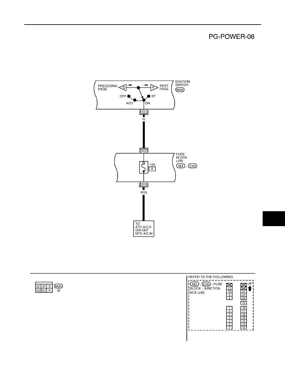
POWER SUPPLY ROUTING CIRCUIT
PG-13
C
D
E
F
G
H
I
J
L
M
A
B
PG
2005 Pathfinder
IGNITION POWER SUPPLY — IGNITION SW. IN ON
WKWA2530E
|
|
|
POWER SUPPLY ROUTING CIRCUIT PG-13 C D E F G H I J L M A B PG
2005 Pathfinder IGNITION POWER SUPPLY — IGNITION SW. IN ON WKWA2530E |