Nissan Pathfinder (2005 year). Manual - part 336
COMBINATION SWITCH
LT-93
C
D
E
F
G
H
I
J
L
M
A
B
LT
2005 Pathfinder
4.
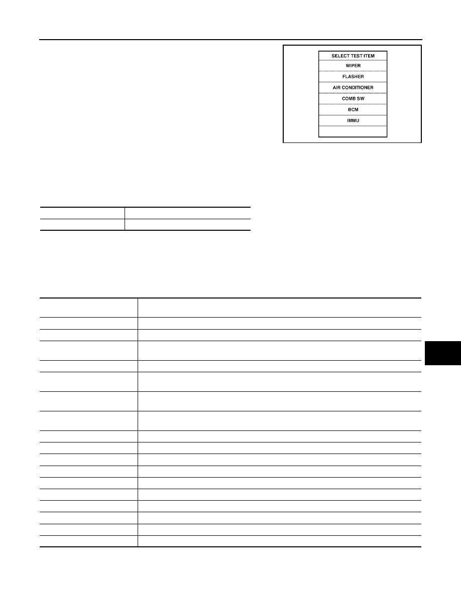
Touch "COMB SW".
DATA MONITOR
Operation Procedure
1.
Touch "COMB SW" on "SELECT TEST ITEM" screen.
2.
Touch "DATA MONITOR" on "SELECT DIAG MODE" screen.
3.
Touch either "ALL SIGNALS" or "SELECTION FROM MENU" on "SELECT MONITOR ITEM" screen.
4.
Touch "START".
5.
When "SELECTION FROM MENU" is selected, touch items to be monitored. When "ALL SIGNALS" is
selected, all the signals will be monitored.
6.
Touch "RECORD" while monitoring, then the status of the monitored item can be recorded. To stop
recording, touch "STOP".
Display Item List
LKIA0283E
ALL SIGNALS
Monitors all the signals.
SELECTION FROM MENU
Selects and monitors individual signal.
Monitor item name
"OPERATION OR UNIT"
Contents
TURN SIGNAL R
"ON/OFF"
Displays "Turn Right (ON)/Other (OFF)" status, determined from lighting switch signal.
TURN SIGNAL L
"ON/OFF"
Displays "Turn Left (ON)/Other (OFF)" status, determined from lighting switch signal.
HI BEAM SW
"ON/OFF"
Displays status (high beam switch: ON/Others: OFF) of high beam switch judged from lighting
switch signal.
HEAD LAMP SW 1
"ON/OFF"
Displays "Headlamp switch 1 (ON)/Other (OFF)" status, determined from lighting switch signal.
HEAD LAMP SW 2
"ON/OFF"
Displays status (headlamp switch 2: ON/Others: OFF) of headlamp switch 2 judged from lighting
switch signal.
LIGHT SW 1ST
"ON/OFF"
Displays status (lighting switch 1st position: ON/Others: OFF) of lighting switch judged from lighting
switch signal.
PASSING SW
"ON/OFF"
Displays status (flash-to-pass switch: ON/Others: OFF) of flash-to-pass switch judged from lighting
switch signal.
AUTO LIGHT SW
"ON/OFF"
Displays "Auto light switch (ON)/Other (OFF)" status, determined from lighting switch signal.
FR FOG SW
"ON/OFF"
Displays "Front fog lamp switch (ON)/Other (OFF)" status, determined from lighting switch signal.
FR WIPER HI
"ON/OFF"
Displays "Front Wiper HI (ON)/Other (OFF)" status, determined from wiper switch signal.
FR WIPER LOW
"ON/OFF"
Displays "Front Wiper LOW (ON)/Other (OFF)" status, determined from wiper switch signal.
FR WIPER INT
"ON/OFF"
Displays "Front Wiper INT (ON)/Other (OFF)" status, determined from wiper switch signal.
FR WASHER SW
"ON/OFF"
Displays "Front Washer Switch (ON)/Other (OFF)" status, determined from wiper switch signal.
INT VOLUME
[1 - 7]
Displays intermittent operation knob setting (1 - 7), determined from wiper switch signal.
RR WIPER ON
"ON/OFF"
Displays "Rear Wiper (ON)/(OFF)" status, determined from wiper switch signal.
RR WIPER INT
"ON/OFF"
Displays "Rear Wiper INT (ON)/(OFF)" status, determined from wiper switch signal.
RR WASHER SW
"ON/OFF"
Displays "Rear Washer (ON)/(OFF)" status, determined from wiper switch signal.