Nissan Pathfinder (2005 year). Manual - part 334
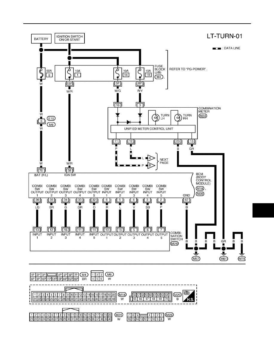
TURN SIGNAL AND HAZARD WARNING LAMPS
LT-77
C
D
E
F
G
H
I
J
L
M
A
B
LT
2005 Pathfinder
Wiring Diagram — TURN —
EKS009L9
WKWA2032E
|
|
|
TURN SIGNAL AND HAZARD WARNING LAMPS LT-77 C D E F G H I J L M A B LT
2005 Pathfinder Wiring Diagram — TURN — EKS009L9 WKWA2032E |