Nissan Pathfinder (2005 year). Manual - part 324
CAN SYSTEM (TYPE 8)
LAN-291
[CAN]
C
D
E
F
G
H
I
J
L
M
A
B
LAN
2005 Pathfinder
9.
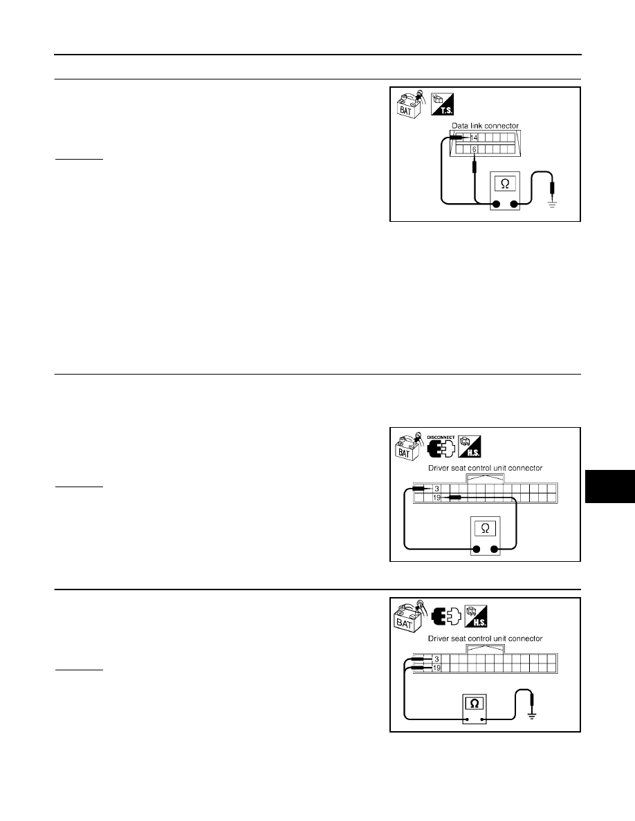
CHECK HARNESS FOR SHORT CIRCUIT
Check continuity between data link connector M22 terminals 6 (L),
14 (P) and ground.
OK or NG
OK
>> GO TO 10.
NG
>> Check the following harnesses. If any harness is dam-
aged, repair the harness.
●
Harness between data link connector and harness
connector M31
●
Harness between data link connector and display control unit
●
Harness between data link connector and front air control
●
Harness between data link connector and steering angle sensor
●
Harness between data link connector and BCM
●
Harness between data link connector and combination meter
●
Harness between data link connector and transfer control unit
●
Harness between data link connector and harness connector M40
●
Harness between data link connector and harness connector M91
10.
CHECK HARNESS FOR SHORT CIRCUIT
1.
Disconnect following connectors.
–
Driver seat control unit connector
–
Harness connector P1
2.
Check continuity between driver seat control unit harness con-
nector P2 terminals 3 (L) and 19 (P).
OK or NG
OK
>> GO TO 11.
NG
>> Repair harness between driver seat control unit and har-
ness connector P1.
11.
CHECK HARNESS FOR SHORT CIRCUIT
Check continuity between driver seat control unit harness connector
P2 terminals 3 (L), 19 (P) and ground.
OK or NG
OK
>> GO TO 12.
NG
>> Repair harness between driver seat control unit and har-
ness connector P1.
6 (L) – Ground
: Continuity should not exist.
14 (P) – Ground
: Continuity should not exist.
PKIA9872E
3 (L) – 19 (P)
: Continuity should not exist.
PKIA6842E
3 (L) – Ground
: Continuity should not exist.
19 (P) – Ground
: Continuity should not exist.
SKIB2818E