Nissan Pathfinder (2005 year). Manual - part 281


  Index      Manuals     Nissan Pathfinder (2005 year) - Service and Repair Manual


Search            copyright infringement  


Content      ..     279      280      281      282     ..


Nissan Pathfinder (2005 year). Manual - part 281


INSIDE MIRROR

GW-55

C

D

E

F

G

H

J

K

L

M

A

B

GW

2005 Pathfinder

INSIDE MIRROR

PFP:96321

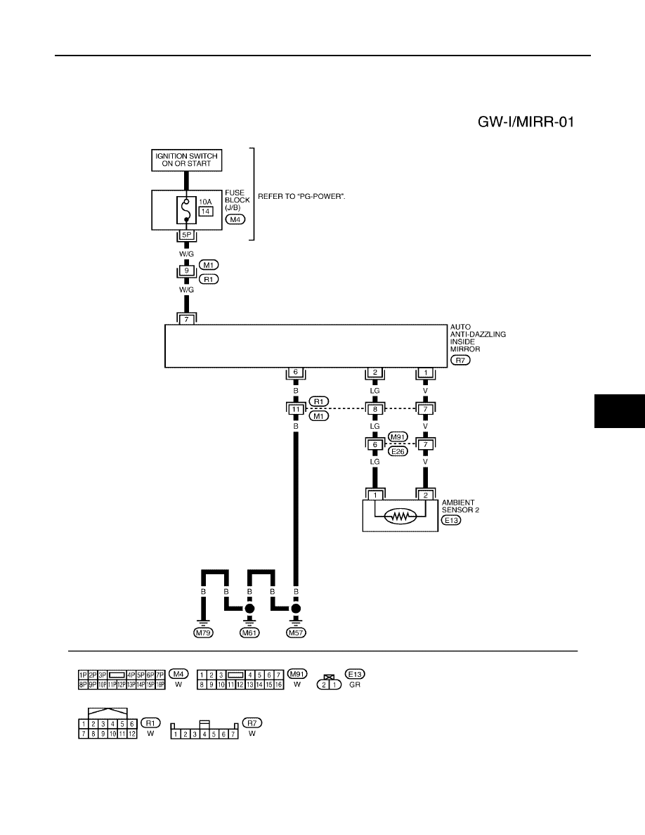
Wiring Diagram — I/MIRR —

EIS0042E

WITHOUT HOMELINK®

WIWA0529E

GW-56

INSIDE MIRROR

2005 Pathfinder

With Homelink®

WIWA0530E

INSIDE MIRROR

GW-57

C

D

E

F

G

H

J

K

L

M

A

B

GW

2005 Pathfinder

Removal and Installation

EIS0042F

INSIDE MIRROR

1.

Remove inside mirror finisher (if equipped).

2.

Slide the mirror upward to remove.

3.

Disconnect the connector (if equipped).

Installation is in the reverse order of removal.

1.

Inside mirror

2.

Inside mirror finisher

LIIA0277E

GW-58

REAR WINDOW DEFOGGER

2005 Pathfinder

REAR WINDOW DEFOGGER

PFP:25350

Component Parts and Harness Connector Location

EIS0042G

System Description

EIS0042H

The rear window defogger system is controlled by BCM (body control module) and IPDM E/R (intelligent
power distribution module engine room).
The rear window defogger only operates for approximately 15 minutes.
Power is supplied at all times

through 15A fuses [No. 43 (with heated mirrors), 46 and 47, located in the IPDM E/R]

to rear window defogger relay

through 50A fusible link [letter , located in the fuse block (J/B)]

to BCM terminal 70.

With the ignition switch turned to ON or START position, power is supplied

through ignition relay

to rear window defogger relay (located in the IPDM E/R)

through 10A fuse [No. 1, located in the fuse block (J/B)]

to BCM terminal 38

through 10A fuse [No. 8, located in the fuse block (J/B)]

to front air control terminal 6.

Ground is supplied

to BCM terminal 67

to front air control terminal 20

through body grounds M57, M61 and M79

LIIA1719E

REAR WINDOW DEFOGGER

GW-59

C

D

E

F

G

H

J

K

L

M

A

B

GW

2005 Pathfinder

to IPDM E/R terminals 38 and 59

through body grounds E9, E15 and E24.

When front air control (rear window defogger switch) is turned to ON, ground is supplied

to BCM terminal 9

through front air control terminal 11

through front air control terminal 20

through body grounds M57, M61 and M79.

Then rear window defogger switch is illuminated.
Then BCM recognizes that rear window defogger switch is turned to ON.
Then it sends rear window defogger switch signals to IPDM E/R via CAN communication (CAN-H, CAN-L)
(with auto A/C).
When IPDM E/R receives rear window defogger switch signals, ground is supplied

to rear window defogger relay (located in the IPDM E/R)

through IPDM E/R terminals 38 and 59

through body grounds E9, E15 and E24

Then rear window defogger relay is energized.
With power and ground supplied, rear window defogger filaments heat and defog the rear window.
When rear window defogger relay is turned to ON (with heated mirrors), power is supplied

through heated mirror relay (located in the IPDM E/R)

through IPDM E/R terminal 23

to door mirror defogger (LH and RH) terminal 1.

Door mirror defogger (LH and RH) is grounded through body grounds M57, M61 and M79.
With power and ground supplied, rear window defogger filaments heat and defog the rear window and door
mirror defogger filaments heat and defog the mirrors.

CAN Communication System Description

EIS0042I

Refer to

LAN-24, "CAN COMMUNICATION"

.

GW-60

REAR WINDOW DEFOGGER

2005 Pathfinder

Schematic

EIS0042J

WIWA0531E

REAR WINDOW DEFOGGER

GW-61

C

D

E

F

G

H

J

K

L

M

A

B

GW

2005 Pathfinder

Wiring Diagram — DEF —

EIS0042K

WIWA0532E

GW-62

REAR WINDOW DEFOGGER

2005 Pathfinder

WIWA0533E


Content      ..     279      280      281      282     ..