Nissan Pathfinder (2005 year). Manual - part 259


  Index      Manuals     Nissan Pathfinder (2005 year) - Service and Repair Manual


Search            copyright infringement  


Content      ..     257      258      259      260     ..


Nissan Pathfinder (2005 year). Manual - part 259


FRONT FINAL DRIVE ASSEMBLY

FFD-15

C

E

F

G

H

I

J

K

L

M

A

B

FFD

2005 Pathfinder

CAUTION:

Do not pull on the ABS sensor harness.
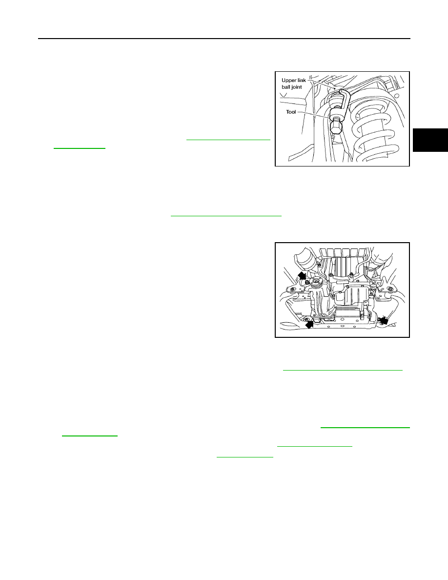
4.

Support the lower link using a suitable jack.

5.

Separate the upper link ball joint stud from the steering knuckle
using Tool.

CAUTION:

Support the lower link using a jack.

6.

Remove the rear engine under cover using power tool.

7.

Drain the front final drive fluid. Refer to

FFD-8, "Changing Differ-

ential Gear Oil"

.

8.

Remove the RH and LH drive shafts from the front final drive
using suitable tool.

CAUTION:

Do not reuse the front final drive side oil seals.

9.

Remove the front crossmember.

10. Disconnect the front propeller shaft from the front final drive. Then reposition the front propeller shaft

aside using suitable wire. Refer to

PR-5, "Removal and Installation"

.

11. Disconnect the vent hose from the front final drive.

12. Support the front final drive using a suitable jack.

13. Remove the front final drive bolts, then remove the front final

drive assembly.

CAUTION:

Support the front final drive using a jack.

INSTALLATION

Installation is the reverse order of removal.

Install new side oil seals into the front final drive assembly. Refer to

FFD-12, "Removal and Installation"

.

CAUTION:

When installing the drive shaft assembly into the front final drive assembly, do not damage the
side oil seal.

Make sure there are no pinched or restricted areas on the breather hose caused by bending or
winding when installing it.

Fill the final drive with recommended gear oil after installation. Refer to

FFD-8, "Changing Differ-

ential Gear Oil"

.

Tighten the upper link ball joint stud nut to specifications. Refer to

FSU-5, "Components"

.

Tighten the wheel nuts to specification. Refer to

WT-6, "Rotation"

.

Tool number

: ST29020001 (J-24319-01)

WEIA0119E

WDIA0145E

FFD-16

FRONT FINAL DRIVE ASSEMBLY

2005 Pathfinder

Disassembly and Assembly

UDS0016H

COMPONENTS

1.

Drive pinion lock nut

2.

Companion flange

3.

Front oil seal

4.

Pinion front bearing

5.

Gear carrier

6.

Side oil seal

7.

Bushing

8.

Side shaft

9.

Side shaft bearing

10. Snap ring

11.

Snap ring

12. Gasket

13. Drain plug

14. Collapsible spacer

15. Pinion rear bearing

16. Pinion height adjusting washer

17. Drive pinion

18. Side bearing adjusting washer

19. Side bearing

20. Side gear thrust washer

21. Side gear

22. Pinion mate shaft

23. Lock pin

24. Pinion mate gear

25. Pinion mate thrust washer

26. Drive gear

27. Differential case

28. Housing spacer

29. Bearing cap

30. Filler plug

31. Rear cover

PDIA0696E

FRONT FINAL DRIVE ASSEMBLY

FFD-17

C

E

F

G

H

I

J

K

L

M

A

B

FFD

2005 Pathfinder

ASSEMBLY INSPECTION AND ADJUSTMENT

Before inspection and adjustment, drain gear oil.

Total Preload Torque

1.

Rotate drive pinion back and forth 2 to 3 times to check for unusual noise and rotation malfunction.

2.

Rotate drive pinion at least 20 times to check for smooth opera-
tion of the bearing.

3.

Measure total preload using Tool.

NOTE:
Total preload torque = Pinion bearing torque + Side bearing
torque

If measured value is out of the specification, disassemble it to
check and adjust each part. Adjust the pinion bearing preload and side bearing preload.
Adjust the pinion bearing preload first, then adjust the side bearing preload.

CAUTION:

Select a side bearing adjusting washer for right and left individually.

Drive Gear Runout

1.

Remove rear cover. Refer to

FFD-21, "Differential Assembly"

.

2.

Fit a dial indicator to the drive gear back face.

3.

Rotate the drive gear to measure runout.

If the runout is outside of the repair limit, check drive gear
assembly condition; foreign material may be caught between
drive gear and differential case, or differential case or drive gear
may be deformed.

CAUTION:

Replace drive gear and drive pinion gear as a set.

Tool number

: ST3127S000 (J-25765-A)

Total preload torque (With oil seal):

1.67 - 2.74 N·m (0.17 - 0.27 kg-m, 15 - 24 in-lb)

PDIA0697E

When the preload torque is greater than specification

On pinion bearings:

Replace the collapsible spacer.

On side bearings:

Use thinner side bearing adjusting washers by the same amount to
each side. Refer to

FFD-37, "Side Bearing Adjusting Washer"

.

When the preload torque is less than specification

On pinion bearings:

Tighten the drive pinion nut.

On side bearings:

Use thicker side bearing adjusting washers by the same amount to
each side. Refer to

FFD-37, "Side Bearing Adjusting Washer"

.

Runout limit:

0.08 mm (0.0031 in) or less

SPD886

FFD-18

FRONT FINAL DRIVE ASSEMBLY

2005 Pathfinder

Tooth Contact

1.

Remove rear cover. Refer to

FFD-21, "Differential Assembly"

.

2.

Apply red lead to drive gear.

CAUTION:

Apply red lead to both the faces of 3 to 4 gears at 4 loca-
tions evenly spaced on drive gear.

3.

Rotate drive gear back and forth several times, check drive pin-
ion gear to drive gear tooth contact.

CAUTION:

Check tooth contact on drive side and reverse side.

SPD357

SDIA0570E

SDIA2549E

FRONT FINAL DRIVE ASSEMBLY

FFD-19

C

E

F

G

H

I

J

K

L

M

A

B

FFD

2005 Pathfinder

4.

If tooth contact is improperly adjusted, follow the procedure
below to adjust the pinion height (dimension X).

If the tooth contact is near the face (face contact), or near the
heel (heel contact), thicken pinon height adjusting washers to
move drive pinion closer to drive gear.
Refer to

FFD-37, "Pinion Height Adjusting Washer"

.

If the tooth contact is near the flank (flank contact), or near the
toe (toe contact), thin pinion height adjusting washers to move
drive pinion farther from drive gear.
Refer to

FFD-37, "Pinion Height Adjusting Washer"

.

Backlash

1.

Remove rear cover. Refer to

FFD-21, "Differential Assembly"

.

2.

Fit a dial indicator to the drive gear face to measure the back-
lash.

If the backlash is outside of the specified value, change the
thickness of side bearing adjusting washer.

CAUTION:

Do not change the total amount of washers as it will change the bearing preload.

SDIA0517E

PDIA0440E

PDIA0441E

Backlash:

0.10 - 0.15 mm (0.0039 - 0.0059 in)

When the backlash is greater than specification:

Make drive gear back side adjusting washer thicker,
and drive gear tooth side adjusting washer thinner by
the same amount. Refer to

FFD-37, "Side Bearing

Adjusting Washer"

.

When the backlash is less than specification:

Make drive gear back side adjusting washer thinner,
and drive gear tooth side adjusting washer thicker by
the same amount. Refer to

FFD-37, "Side Bearing

Adjusting Washer"

.

SPD513

FFD-20

FRONT FINAL DRIVE ASSEMBLY

2005 Pathfinder

Companion Flange Runout

1.

Fit a dial indicator onto the companion flange face (inner side of
the propeller shaft bolt holes).

2.

Rotate companion flange to check for runout.

3.

Fit a test indicator to the inner side of companion flange (socket
diameter).

4.

Rotate companion flange to check for runout.

5.

If the runout value is outside the runout limit, follow the proce-
dure below to adjust.

a.

Rotate the companion flange on the drive pinion by 90

°

, 180

°

and 270

°

, while checking for the position

where the runout is minimum.

b.

If the runout value is still outside of the limit after the phase has been changed, possible cause will be an
assembly malfunction of drive pinion and pinion bearing or a malfunctioning pinion bearing.

c.

If the runout value is still outside of the limit after repair of the assembly of drive pinion and pinion bearing
or pinion bearing, replace the companion flange.

DISASSEMBLY
Side Shaft

1.

Drain gear oil, if necessary.

2.

Remove side oil seal.

CAUTION:

Do not damage gear carrier.

3.

Remove snap ring (hole side) using suitable tool.

4.

Remove side shaft assembly out of gear carrier using suitable
tool.

NOTE:
Tap on side shaft assembly from side gear side.

5.

Remove snap ring (shaft side).

Runout limit:

0.1 mm (0.004 in) or less

Runout limit:

0.1 mm (0.004 in) or less

PDIA0698E

PDIA0713E

PDIA0714E

PDIA0715E

FRONT FINAL DRIVE ASSEMBLY

FFD-21

C

E

F

G

H

I

J

K

L

M

A

B

FFD

2005 Pathfinder

6.

Press side shaft out of side shaft bearing.

CAUTION:

Do not drop side shaft.

Differential Assembly

1.

Remove side shaft assembly. Refer to

FFD-20, "Side Shaft"

.

2.

Remove rear cover bolts.

3.

Separate the rear cover from the gear carrier using Tool.

CAUTION:

Do not damage the mating surface.

Do not insert flat-bladed screwdriver, this will damage the
mating surface.

4.

For proper reinstallation, paint matching marks on one side of
the bearing cap.

CAUTION:

For matching mark, use paint. Do not damage bearing
caps and gear carrier.

Bearing caps are line-board during manufacture. The
matching marks are used to reinstall them in their origi-
nal positions.

5.

Remove bearing caps.

PDIA0718E

Tool number

: KV10111100 (J-37228)

PDIA0699E

PDIA0700E

PDIA0701E

FFD-22

FRONT FINAL DRIVE ASSEMBLY

2005 Pathfinder

6.

Lift differential case assembly out using suitable tool.

CAUTION:

Keep side bearing outer races together with inner race.
Do not mix them up.

Keep side bearing adjusting washers together with bear-
ings.

7.

Remove housing spacer.

8.

Remove side bearing inner races, using Tools.

CAUTION:

Place copper plates between the side bearing and drive
gear and the vise to prevent damage.

Do not remove side bearing inner race unless it is being
replaced.

9.

For proper reinstallation, paint matching mark on one side of dif-
ferential case assembly.

CAUTION:

Use paint for matching mark. Do not damage differential
case or drive gear.

10. Remove drive gear bolts.
11. Tap drive gear off differential case assembly using suitable tool.

CAUTION:

Tap evenly all around to keep drive gear from bending.

PDIA0547E

SPD919

Tool number

A: ST33051001 (J-22888-20)

B: ST33061000 (J-8107-2)

PDIA0827E

PDIA0496E


Content      ..     257      258      259      260     ..