Nissan Pathfinder (2005 year). Manual - part 239


  Index      Manuals     Nissan Pathfinder (2005 year) - Service and Repair Manual


Search            copyright infringement  


Content      ..     237      238      239      240     ..


Nissan Pathfinder (2005 year). Manual - part 239


INTAKE MANIFOLD COLLECTOR

EM-17

C

D

E

F

G

H

I

J

K

L

M

A

EM

2005 Pathfinder

REMOVAL

WARNING:

To avoid the danger of being scalded, never drain engine coolant when engine is hot.

1.

Remove engine cover. Refer to

EM-12, "REMOVAL"

.

2.

Remove air cleaner case (upper) with mass air flow sensor and air duct assembly. Refer to

EM-15,

"REMOVAL"

.

3.

Remove electric throttle control actuator as follows:

a.

Drain engine coolant, or when water hoses are disconnected, attach plug to prevent engine coolant leak-
age. Refer to

MA-13, "Changing Engine Coolant"

.

CAUTION:

Perform when engine is cold.

Do not spill engine coolant on drive belt.

b.

Disconnect water hoses from electric throttle control actuator.

When engine coolant is not drained from radiator, attach plug to water hoses to prevent engine coolant
leakage.

c.

Disconnect harness connector.

d.

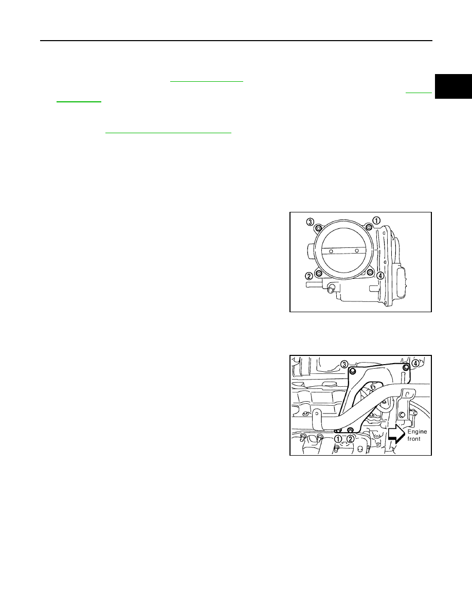
Loosen bolts in reverse order as shown.

CAUTION:

Handle carefully to avoid any shock to electric throttle
control actuator.

Do not disassemble.

4.

Remove the following parts:

Vacuum hose (to brake booster)

PCV hose

5.

Loosen bolts in reverse order as shown to remove intake mani-
fold collector support.

6.

Disconnect EVAP hoses and harness connector from EVAP canister purge volume control solenoid valve.

7.

Remove EVAP canister purge volume control solenoid valve.

8.

Remove VIAS control solenoid valve and vacuum tank.

Add mating marks as necessary for easier installation.

PBIC2875E

PBIC2876E

EM-18

INTAKE MANIFOLD COLLECTOR

2005 Pathfinder

9.

Loosen nuts and bolts in reverse order as shown with power
tool, and remove intake manifold collector.

CAUTION:

Cover engine openings to avoid entry of foreign materials.

INSTALLATION

Installation is in the reverse order of removal. Note the following:

Intake Manifold Collector

If stud bolts were removed from intake manifold, install them and tighten to the specified torque.

Tighten nuts and bolts in numerical order as shown.

Electric Throttle Control Actuator

Tighten bolts in numerical order as shown.

Perform the “Throttle Valve Closed Position Learning” when har-
ness connector of electric throttle control actuator is discon-
nected. Refer to

EC-88, "Throttle Valve Closed Position

Learning"

.

Perform the “Idle Air Volume Learning” and “Throttle Valve
Closed Position Learning” when electric throttle control actuator
is replaced. Refer to

EC-89, "Idle Air Volume Learning"

.

PBIC2877E

Intake manifold collector
bolts and nuts

: 11.0 N·m (1.1 kg-m, 8 ft-lb)

Stud bolts

: 6.9 N·m (7.0kg-m, 61 in-lb)

PBIC2877E

PBIC2875E

INTAKE MANIFOLD

EM-19

C

D

E

F

G

H

I

J

K

L

M

A

EM

2005 Pathfinder

INTAKE MANIFOLD

PFP:14003

Removal and Installation

EBS00NJP

REMOVAL

1.

Release fuel pressure. Refer to

EC-91, "FUEL PRESSURE RELEASE"

.

2.

Remove intake manifold collector. Refer to

EM-17, "REMOVAL"

.

3.

Remove fuel tube and fuel injector assembly. Refer to

EM-34, "REMOVAL"

.

4.

Loosen nuts and bolts with power tool in reverse order as shown
to remove intake manifold.

5.

Remove gaskets.

CAUTION:

Cover engine openings to avoid entry of foreign materials.

INSPECTION AFTER REMOVAL
Surface Distortion

Check the surface distortion of the intake manifold mating sur-
face with straightedge and feeler gauge.

If it exceeds the limit, replace intake manifold.

1.

Intake manifold

2.

Gasket

PBIC2878E

PBIC2879E

Limit

: 0.1 mm (0.004 in)

PBIC0870E

EM-20

INTAKE MANIFOLD

2005 Pathfinder

INSTALLATION

Installation is in the reverse order of removal. Note the following:

Intake Manifold

If stud bolts were removed from cylinder head, install them and tighten to the specified torque.

Tighten all nuts and bolts to the specified torque in two or more
steps in numerical order as shown.

Intake manifold studs

: 11.0 N·m (1.1kg-m, 8 ft-lb)

Intake manifold bolt and nuts

1st step

: 7.4 N·m (0.75 kg-m, 5 ft-lb)

2nd step and after

: 29.0 N·m (3.0 kg-m, 21 ft-lb)

PBIC2879E

EXHAUST MANIFOLD AND THREE WAY CATALYST

EM-21

C

D

E

F

G

H

I

J

K

L

M

A

EM

2005 Pathfinder

EXHAUST MANIFOLD AND THREE WAY CATALYST

PFP:14004

Removal and Installation

EBS00NJQ

REMOVAL (LEFT BANK)

1.

Remove air cleaner case and air duct. Refer to

EM-15, "REMOVAL"

.

2.

Remove engine undercover with power tool.

3.

Disconnect harness connector and remove heated oxygen sen-
sor 2 on both banks using Tool.

CAUTION:

Be careful not to damage heated oxygen sensor 2.

Discard any heated oxygen sensor 2 which has been
dropped from a height of more than 0.5 m (19.7 in) onto a
hard surface such as a concrete floor; replace with a new
sensor.

4.

Remove center exhaust tube, main muffler and left front exhaust tube. Refer to

EX-4, "REMOVAL"

.

5.

Remove exhaust manifold cover (left bank).

1.

Exhaust manifold cover (right bank)

2.

Exhaust manifold (right bank)

3.

Gasket

4.

Exhaust manifold cover (left bank)

5.

Exhaust manifold (left bank)

PBIC2880E

Tool number

: KV10114400 (J-38365)

LBIA0446E

EM-22

EXHAUST MANIFOLD AND THREE WAY CATALYST

2005 Pathfinder

6.

Disconnect harness connector and remove air fuel ratio sensor
1 (left bank) using Tool.

CAUTION:

Be careful not to damage air fuel ratio sensor 1.

Discard any air fuel ratio sensor 1 which has been
dropped from a height of more than 0.5 m (19.7 in) onto a
hard surface such as a concrete floor; replace with a new
sensor.

7.

Remove three way catalyst (left bank).

8.

Loosen nuts with power tool in reverse order as shown.

NOTE:
Disregard the numerical order No. 7 and 8 in removal.

9.

Remove gaskets.

CAUTION:

Cover engine openings to avoid entry of foreign materials.

INSPECTION AFTER REMOVAL
Surface Distortion

Check the surface distortion of the exhaust manifold mating sur-
face with straightedge and feeler gauge.

If it exceeds the limit, replace exhaust manifold.

Tool number

:

(J-44626)

LBIA0447E

PBIC2881E

Limit

: 0.3 mm (0.012 in)

PBIC1096E

EXHAUST MANIFOLD AND THREE WAY CATALYST

EM-23

C

D

E

F

G

H

I

J

K

L

M

A

EM

2005 Pathfinder

INSTALLATION (LEFT BANK)

Installation of the remaining components is in the reverse order of removal. Note the following:

Exhaust Manifold Gasket

Install in direction as shown.

Exhaust Manifold

If stud bolts were removed, install them and tighten to the specified torque.

Install exhaust manifold and tighten nuts in numerical order as
shown.
NOTE:
Tighten nuts No. 1 and 2 in two steps. The numerical order No. 7
and 8 shown second step.

Heated Oxygen Sensor

CAUTION:

Before installing a new air fuel ratio sensor 1 and heated oxygen sensor 2, clean exhaust system
threads using oxygen sensor thread cleaner and apply anti-seize lubricant.

Do not over torque air fuel ratio sensor 1 and heated oxygen sensor 2. Doing so may cause dam-
age to air fuel ratio sensor 1 and heated oxygen sensor 2, resulting in the “MIL” coming on.

PBIC2882E

Exhaust manifold stud torque

: 14.7 N·m (1.5 kg-m, 11 ft-lb)

PBIC2881E

Tool number

: (

) J-43897-12

: (

) J-43897 18

EM-24

EXHAUST MANIFOLD AND THREE WAY CATALYST

2005 Pathfinder

REMOVAL (RIGHT BANK)

1.

Remove engine assembly. Refer to

EM-104, "REMOVAL"

.

2.

Loosen nuts with power tool in reverse order as shown.

NOTE:
Disregard the numerical order No. 7 and 8 in removal.

3.

Remove gaskets.

CAUTION:

Cover engine openings to avoid entry of foreign materials.

INSPECTION AFTER REMOVAL
Surface Distortion

Check the surface distortion of the exhaust manifold mating sur-
face with straightedge and feeler gauge.

If it exceeds the limit, replace exhaust manifold.

PBIC2881E

Limit

: 0.3 mm (0.012 in)

PBIC1096E


Content      ..     237      238      239      240     ..