Nissan Pathfinder (2005 year). Manual - part 230
REFRIGERANT PRESSURE SENSOR
EC-691
C
D
E
F
G
H
I
J
K
L
M
A
EC
2005 Pathfinder
REFRIGERANT PRESSURE SENSOR
PFP:92136
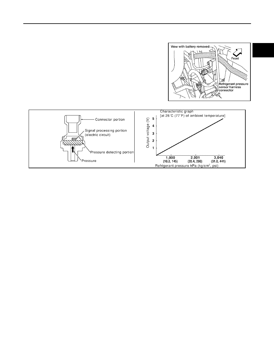
Component Description
UBS00KII
The refrigerant pressure sensor is installed at the liquid tank of the
air conditioner system. The sensor uses an electrostatic volume
pressure transducer to convert refrigerant pressure to voltage. The
voltage signal is sent to ECM, and ECM controls cooling fan system.
BBIA0564E
SEF099XA